#include <stdbool.h>
#include <stdint.h>
#include <stdio.h>
#include "app_uart.h"
#include "app_error.h"
#include "nrf_delay.h"
#include "nrf.h"
#include "bsp.h"
#if defined (UART_PRESENT)
#include "nrf_uart.h"
#endif
#if defined (UARTE_PRESENT)
#include "nrf_uarte.h"
#endif


//#define ENABLE_LOOPBACK_TEST  /**< if defined, then this example will be a loopback test, which means that TX should be connected to RX to get data loopback. */

#define MAX_TEST_DATA_BYTES     (15U)                /**< max number of test bytes to be used for tx and rx. */
#define UART_TX_BUF_SIZE 256                         /**< UART TX buffer size. */
#define UART_RX_BUF_SIZE 256                         /**< UART RX buffer size. */

void uart_error_handle(app_uart_evt_t * p_event)
{
    if (p_event->evt_type == APP_UART_COMMUNICATION_ERROR)
    {
        APP_ERROR_HANDLER(p_event->data.error_communication);
    }
    else if (p_event->evt_type == APP_UART_FIFO_ERROR)
    {
        APP_ERROR_HANDLER(p_event->data.error_code);
    }
}


#ifdef ENABLE_LOOPBACK_TEST
/* Use flow control in loopback test. */
#define UART_HWFC APP_UART_FLOW_CONTROL_ENABLED

/** @brief Function for setting the @ref ERROR_PIN high, and then enter an infinite loop.
 */
static void show_error(void)
{

    bsp_board_leds_on();
    while (true)
    {
        // Do nothing.
    }
}


/** @brief Function for testing UART loop back.
 *  @details Transmitts one character at a time to check if the data received from the loopback is same as the transmitted data.
 *  @note  @ref TX_PIN_NUMBER must be connected to @ref RX_PIN_NUMBER)
 */
static void uart_loopback_test()
{
    uint8_t * tx_data = (uint8_t *)("\r\nLOOPBACK_TEST\r\n");
    uint8_t   rx_data;

    // Start sending one byte and see if you get the same
    for (uint32_t i = 0; i < MAX_TEST_DATA_BYTES; i++)
    {
        uint32_t err_code;
        while (app_uart_put(tx_data[i]) != NRF_SUCCESS);

        nrf_delay_ms(10);
        err_code = app_uart_get(&rx_data);

        if ((rx_data != tx_data[i]) || (err_code != NRF_SUCCESS))
        {
            show_error();
        }
    }
    return;
}
#else
/* When UART is used for communication with the host do not use flow control.*/
#define UART_HWFC APP_UART_FLOW_CONTROL_DISABLED
#endif


/**
 * @brief Function for main application entry.
 */
int main(void)
{
    uint32_t err_code;

    bsp_board_init(BSP_INIT_LEDS);

    const app_uart_comm_params_t comm_params =
      {
          RX_PIN_NUMBER,
          TX_PIN_NUMBER,
          RTS_PIN_NUMBER,
          CTS_PIN_NUMBER,
          UART_HWFC,
          false,
#if defined (UART_PRESENT)
          NRF_UART_BAUDRATE_115200
#else
          NRF_UARTE_BAUDRATE_115200
#endif
      };

    APP_UART_FIFO_INIT(&comm_params,
                         UART_RX_BUF_SIZE,
                         UART_TX_BUF_SIZE,
                         uart_error_handle,
                         APP_IRQ_PRIORITY_LOWEST,
                         err_code);

    APP_ERROR_CHECK(err_code);

#ifndef ENABLE_LOOPBACK_TEST
    printf("\r\nUART example started.\r\n");

    while (true)
    {
        uint8_t cr;
        while (app_uart_get(&cr) != NRF_SUCCESS);
        while (app_uart_put(cr) != NRF_SUCCESS);

        if (cr == 'q' || cr == 'Q')
        {
            printf(" \r\nExit!\r\n");

            while (true)
            {
                // Do nothing.
            }
        }
    }
#else

    // This part of the example is just for testing the loopback .
    while (true)
    {
        uart_loopback_test();
    }
#endif
}


/** @} */
Above is the code that im using.
Module - BT832x
Debugger - Segger J-link
IDE - Segger IDE
SDK - nRF5_SDK_17.0.2_d674dde (Downloaded from nordic website)
Program used - \nRF5_SDK_17.0.2_d674dde\examples\peripheral\uart\pca10040\blank\ses\uart_pca10040
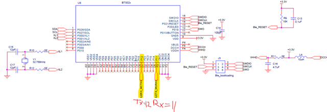
TXD pin - P0.11 (BT832x module)
RXD pin - P0.12 (BT832x module)
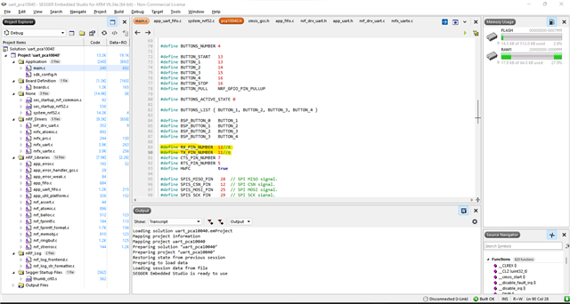
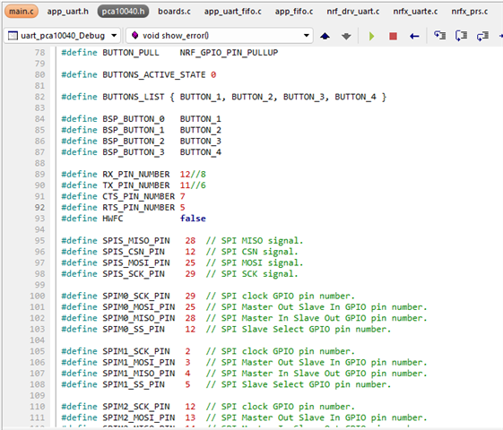
The UART example SDK code uses #define RX_PIN_NUMBER 8 and #define TX_PIN_NUMBER 6 but in my custom board Im using TX pin as P0.11 and RXD as P0.12.
So I changed the Pin numbers as 12 and 11 in the pca10040.h and tried executing the UART doesnt responds.

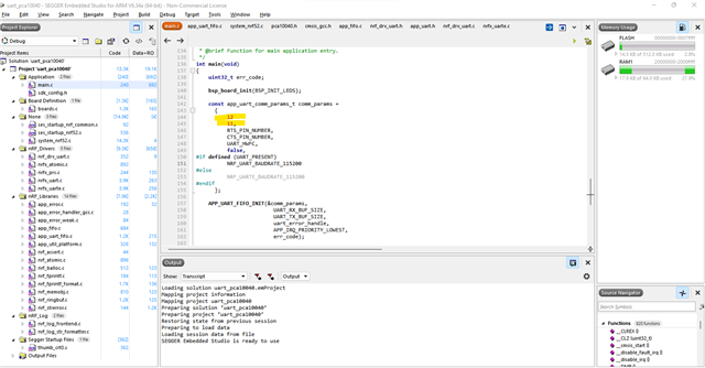
Then I tried to change in the main.c under "const app_uart_comm_params_t comm_params" as well its still not responding.

Is there anything else am I missing ? Please help me out. Im totally new to nRF.
Below is the schematics for the BT832x module.

Thank you in advance


