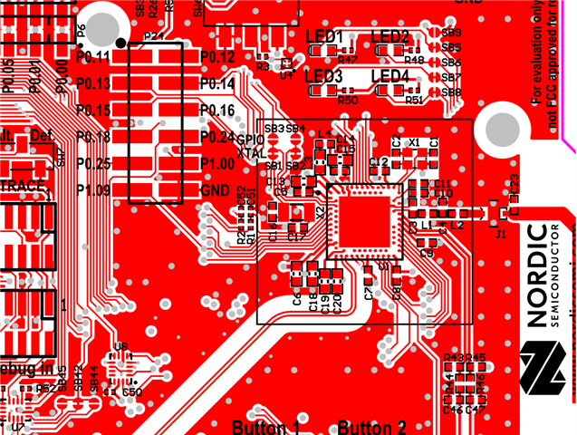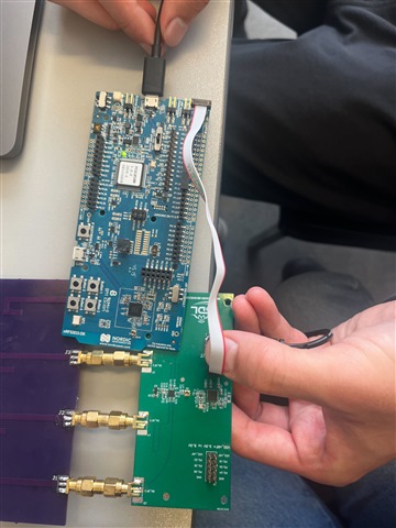
issues when flashing a custom board using nrf52833dk debug port P19

test setup

the custom board schematic
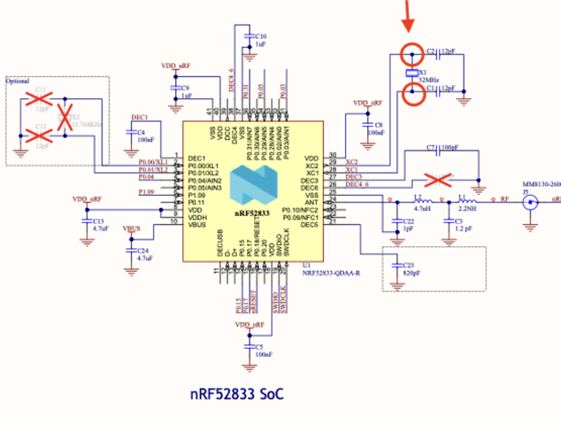
we tried to flash the custom board with the beacon sample here https://developer.nordicsemi.com/nRF_Connect_SDK/doc/latest/zephyr/samples/bluetooth/beacon/README.html

Connect debug out header P19 on DK to jtag-style connector on custom board. Connect custom board to power supply.

Testing as follows:

1.Program the 52833 chip on the dk without the connection above

Result:  success, DK beacons as expected

2.Program the 52833 chip on the dk with the connection above, but do not power the custom board

Result: success, DK beacons as expected. Custom board does not beacon as it is not powered.

3.Program the 52833 chip on the custom board with connection above and power.

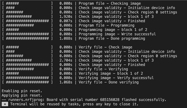
Result: DK does not beacon, setup programs custom board only. Successfully program the custom board with no errors in VSCode when connecting or flashing. However, board is till not beaconing at all.

The VS code message for the third test
We then examined the voltage of the chip

Following measurements were done:

Measurement

DK Result

Custom Board Result

Voltage at DEC1

1.1 V

0.75V

Voltage at Vbus

0V

< 0.001V

Following these results, capacitor C24 in our custom board was removed. No difference in measure Voltage was observed. Custom board is still not functional.

Question:

1. did we have a correct setup to flash the custom board

2. what could be the reason that Voltage at DEC1 is not correct on our custom board

Thank you for reading through this problem.

Parents Reply
  • Hello Jared,

    We are done making the changes for the design. Can you please do a review of the new design for all nRF52833 related aspects for both schematic and layout? Schematic PDF and PCB layout file are located at: drive.google.com/.../1r2U6VuMSvopTMpycXYjjW5caeOkVX0NH

    Also, we have two questions on the design:

    1) To access reset signal we have connected it to pin AD12 and fanned it(reset) out through that pad. Is that OK to do or will it cause any issue while programming the boards? The other thing we can do it cover that pad with solder mask or remove it entirely from the footprint. Do you have any previous knowledge of such implementation in any designs?

    2) We are planning to operate the design in high voltage mode, i.e. VDDH powered, what should be the supply connected to cJTAG programming header in that case? VDDH or VDD? My understanding is that VDD will be disabled in high-voltage mode. Is that correct or VDD will be regulated internally through nRF52833?

    Thanks.

Children
  • Hi,


    I will cover for Jared on this case today. 

    This looks better but some feedback:
    1. Can you route the connection between the DEC4 and DEC6 so that it does not go under the 32 MHz crystal routing, and not spilt up the center pad of the nRF?
    2. What types of antennas will you use? Is this meant to be used for AoA? What will be the spacing between the antennas?


    George Shaker said:
    1) To access reset signal we have connected it to pin AD12 and fanned it(reset) out through that pad. Is that OK to do or will it cause any issue while programming the boards? The other thing we can do it cover that pad with solder mask or remove it entirely from the footprint. Do you have any previous knowledge of such implementation in any designs?

    - See pin reset in the ps

    George Shaker said:
    2) We are planning to operate the design in high voltage mode, i.e. VDDH powered, what should be the supply connected to cJTAG programming header in that case? VDDH or VDD? My understanding is that VDD will be disabled in high-voltage mode. Is that correct or VDD will be regulated internally through nRF52833?

    - If your planning to use high voltage mode, when you need to change the configuration on the VDD/VDDH set up and use Circuit configuration no. 4 schematic for QIAA aQFNTm73 as reference.
    - VDD  should be connected to the JTAG

    Best regards,
    Kaja

  • Hello,

    Thank you for reviewing the design and providing feedback. We have done the suggested changes.

    Yes, this design will be used for AoA application and we will be using custom 4-Antenna Array with this board.  The Antenna feed points are 30.6 mm apart and all four antenna are having the same structure.

    Do you have any guidelines or any recommendations for the Antenna Array for AoA application?

    Thanks.

  • Okay, 

    no wo don't have any recommendations on this. 


    See our DF info and DF central ex , DF connection less locator and DF connectionless beacon

    our example is with a 12 patch antenna matrix.

    Best regards,
    Kaja

Related