PSM floor current is 60uA not 4uA

Hi there, 

We are running a power consumption test using PSM mode, and we are however not measuring the 4uA floor current as expected.

We are requesting a active time of 6 minutes, and TAU time of 30minutes. We are also using eDRX.

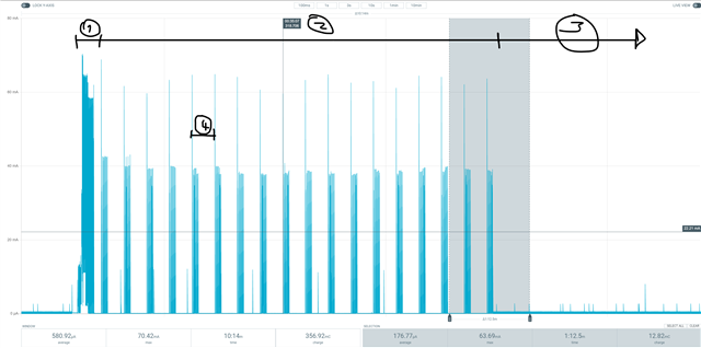
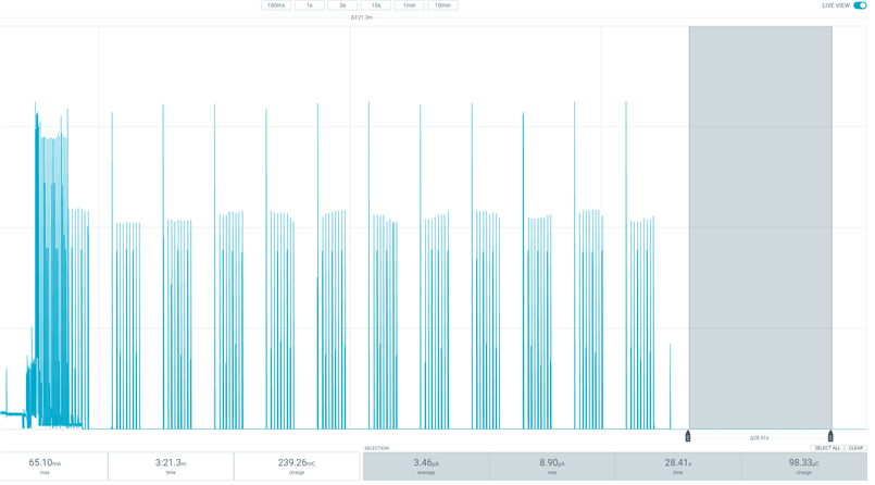
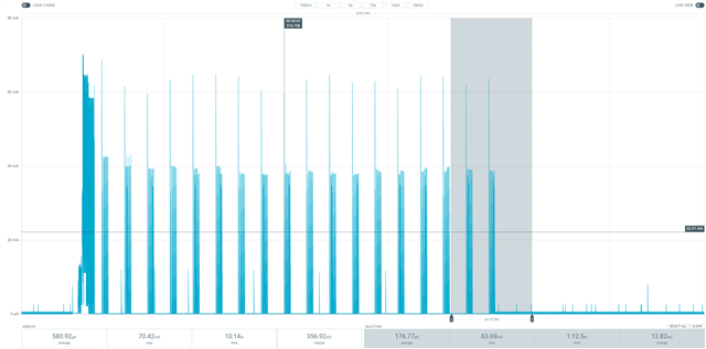
However after the active time has passed, the device does not go into a low power state. There also appears to be a lot of noise:

I can confirm that the network does assign us the correct timers, as we get the following message in:

+CEREG: 1,"0001","01A2D002",7,,,"00100110","11100000"

Kindly advise what can be the issue here?

Parents
  • I guess, if you check GSMA Energy Efficiency for Mobile IoT , page 11, figure 1, you will recognize the difference between "active time" (T3324, or ) and "Inactivity timer". Others use the terms "PSM Activity Timer" and "RRC Activity Timer". So you selected the phase when switching from RRC Connected to Idle, but sleeping is the reached after Idle (in you case 6 minutes). Just wait and measure later.

  • Hi Achim,

    I did not select the phase where it goes from RRC connect to Idle. I selected the phase during which idle time (as you can see in the figure, 6 minutes of multiple eDRX cycles occured) goes to sleeping. The "inactivity timer" is present in the very first spike, I am just zoomed out a lot.

    I have waited more than the 30minutes periodic TAU, which comes in successfully after 30minutes as expected. So I guess there is indeed an issue with the PSM.

    The current in the sleeping state sits around 60uA.

  • Hi Dejans,

    Thanks for your response. We have done these tests multiple times in the past (prob a year ago) and we are revisiting the usage of PSM mode. I do understand the different states regarding the inactivity time when in RRC connected,  RRC idle as well as PSM. We are definitely entering PSM mode in the graph of my original post.

    Section 1 is the attach process, which includesthe RRC inactivity timer of around 3seconds. Section 2 is the entire RRC Idle time of 6 minutes as requested, Section 3 onward is then supposed to be PSM mode, where we measure 60-70uA instead of the expected 4uA. Section 4 is the edrx cycles of 10.24sec. After 30minutes, which was the requested periodic TAU using +CPSMS, we do see the TAU on the profile indicating that we were indeed in PSM mode.

    Our setup is using the PPK2 in source meter mode at 3.6V, as specified in the doc Achim linked. I also ran the low power test by uploading the .hex file in the link of the doc, and we are able to measure 3uA with that.

    We are running the stock Serial LTE Modem application with modem fw version 1.3.1, and we then send some at commands using the LTE Link Monitor app.

  • > we are able to measure 3uA with that.

    Great, so your setup and device is well.

    > Serial LTE Modem 

    Hm, AFAIK, that uses the UART, does it?

    The standard UART consumes quite a lot, so 60uA seems to be a brilliant value.

  • We turned of the UART using the #XSLEEP cmd, so it cant be the UARTs. I was thinking it might be the SIM card that is still active? Will investigate this further.

  • HI Achim/Dejans,

    I have been able to confirm that the issue is in the Serial LTE Modem application. In the past we have created this ticket, in which  have been able to assist us. There seems to be some a setting that can be disabled/emnabled in the serial lte modem application in order to be able to go into a low power state of 4uA.

    When we upload the 8547.merged.hex file and run it, we are able to go into u 4uA sleep state:

    Possible to advise how to edit the serial lte modem application in order to go into a low power state? We will be using this application in our product as we will be controlling the modem from an external MCU.

    From the ticket:

    Hi, sorry for the late reply. Here a hex file for you: 3005.merged.hex

    It is currently consuming 30 uA in idle, after calling AT#XSLEEP=0, ideally you should see around 2-3 uA. So I will have to look into what changes they made in the newest NCS release v1.6.0 in order to get it down to the expected idle current. Anyways, you should be able to get started with the hex I posted above, and I will get back to you shortly with an updated one.

  • Hi Frikkie,

    In your picture, there is an average current in the selected area of 176.77uA. Could you show the picture where you got 60uA and which area you selected when you got 60uA? 

    For comparison, have you tried simulating the current consumption with Online Power Profiler? What are the results? Could you show the results? Could you show the values used?

    How long is your PSM interval?

    Was SIM card in the board when you performed measurement?

    You can check if you have entered PSM mode and SIM card consumption by following this guide. In addition, ensure that logging over serial port is disabled. Some peripherals might also cause elevated currents. 

    Best regards,
    Dejan

Reply Children
  • Hi Dejan,

    Again, in my picture, section 3 is the PSM section, which draws a current of 60uA. As mentioned in the original post, the periodic TAU is 30mins and active time is 6minutes.

    The SIM cards was off course in the board, otherwise we would not be able to attach to the network and get a message of +CEREG: 1,"0001","01A2D002",7,,,"00100110","11100000".

    I do not see how the online power profiler is going to make any difference. We are supposed to measure 4uA in PSM mode and we are not.

    As mentioned the problem is clearly in the serial lte modem application. It would be great if we can get  to provide his insights on this issue, as he has been able to fix this for us before.

  • Hi Frikkie,

    Which voltage and current levels do you have on SIM_1V8 pin (pin 49, according to the Testing UICC interface as GPIO documentation)?

    Best regards,
    Dejan

  •   I have had a problem with similar symptoms before. It required a lot of digging but eventually I found out that it was an issue with the SIM card itself - the SIM card was configured to report that it supported the UICC SUSPEND command, but in reality it rejected the command when it was sent. The nrf91 modem firmware then did not power off the SIM card (ignoring that the SIM reported an error) and went to sleep, and then the SIM was basically left on in sleep mode causing about 50uA of current draw.

    Have you tried measuring the SIM current on the nrf9160dk? There is a special header for it next to the SIM card socket.

    In my case, this was with a custom SIM card that is used with a cellular network emulator, so it was of course a bit of an unusual situation. Have you tried testing with a SIM card from a completely different carrier? Once I fixed this issue with the SIM, I could get down to about 4uA or so.

  • > When we upload the 8547.merged.hex file and run it, we are able to go into u 4uA sleep state:

    If it's the SIM, I guess, this firmware doesn't switch to sleeping, it switches off. On the other side, if it switches to sleeping and not off, then the SIM card should not be the issue.

    Looking forward to the outcome using the Serial LTE Modem of a newer NCS. There you can select between sleeping and switching off (just to mention: I don't know, why nordic chose the term "sleeping" for +CFUN=0, but anyway, we will see, what their "sleep" and "idle" will bring.)

  • Hi  , there are usually three things that can cause around 30-60 uA in idle:

    1. UART ENABLE. The serial LTE modem sample uses UART0 for the AT interface by default. That means that UART0 will turn off with the AT#XSLEEP=2. However, UART1 and UART2 could still be running, and might have to be switched off as well.

      You can do this through the .overlay file (boards/nrf9160dk_nrf9160_ns.overlay). In this file you can see that UART2 is switched on by default.
      &uart2 {
          compatible = "nordic,nrf-uarte";
          current-speed = <115200>;
          status = "disabled";
          tx-pin = <10>;
          rx-pin = <11>;
          rts-pin = <12>;
          cts-pin = <13>;
          hw-flow-control;
      };
      &uart1 {
          status = "disabled";
      };
    2. GPIOTE IN event. The IN event is not used by the serial LTE modem sample by default, but if you modify the code and add an other wake up pin or similar, you may have enabled the IN event on this pin. Here is an example on how you can use the low power SENSE event instead of the IN event on pin P0.06 and pin P0.07, using the .overlay file:
      &gpio0 {
          sense-edge-mask = <(1 << 6) | (1 << 7)>;
      };
    3. SIM. The SIM card is powered by the SIM_1V8 pin on the nRF91. If this line is 1.8V it means that the SIM has not been shut down, and is still probably in clock stop mode consuming around 30-60 uA. The only way to shut down the SIM is to cut the power, which means that the SIM_1V8 pin will be 0V.

      The modem should automatically cut the power during PSM. However, there are cards in the market that switches profiles based on a timeout from the modem. The nRF91 will not deactivate the card if the card has requested a timer and a timer is still running. So unfortunately some SIMs will never allow the nRF91 to cut the power. This is probably what experienced with the SIM he tested.

      Whether or not this is the reason for the additional 60uA can be easily checked by measuring the voltage on SIM_1V8. It must be 0V, otherwise the SIM will consume power.

    Best regards,
    Stian

Related