
nRF connect SDK v 2.1.1 using visual studio code.
Hei helsing
A few busy weeks here, however I've finally tested some more in regards to previous question found under your guide on the forum:
small-i2c-oled-displays-using-nrf-connect-sdk
To summarize the problem Im trying to get a 160x80 pixel (Width x Height) TFT display with the ST3375 driver to work with the nrf9160 over SPI.
The specific display can be found here: TFT 160x80 SPI - RS components
Ive tested the TFT with an ESP32-C3 mini in the Arduino environment and confirmed that the display is working fine with same wiring as used for the nrf9160 setup.
For the nrf9160 setup, upon probing the SPI signals I see that MOSI, CLK, CS, RESET and CMD pins are giving nice 3v3 signals. (I had to switch the RESET and CMD pins from the previous gpio0 8 and gpio0 9 as these did not produce any output.
However the result I get on the TFT display is still just garbage.
Ive played around with lowering the SPI max frequency but without any luck.
I can see that the idle state of the data signal (MOSI) is 3v3 as opposed to 0v in the ESP32 test. I don't think the problem lays here, but just as a note, what would be the best way to define CPOL/CPHA in code when using the ST7735 driver. Would this be done in the .overlay file?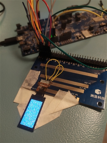
TFT alive but not making sense.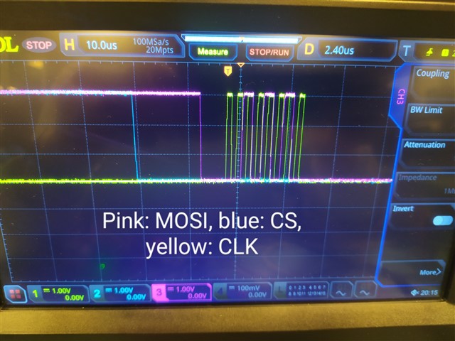
The above is the first byte clocked in when writing to the TFT display. 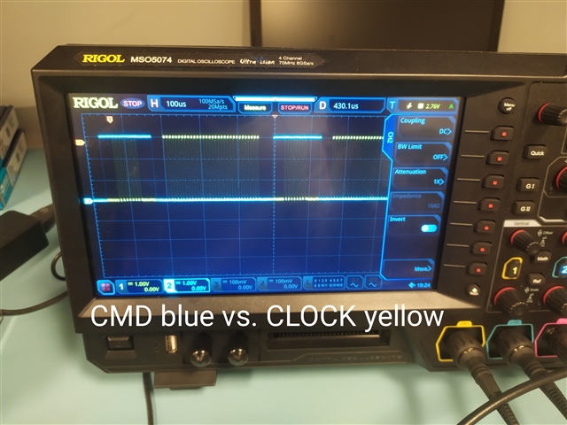
The above shows the command (CMD) signal in blue and the CLK signal in yellow around midways in a SPI write session.
The .overlay code:
 / {
	chosen {
		zephyr,display = &st7735r_st7735r_ada_160x128;
	};
};

&arduino_spi {
	compatible = "nordic,nrf-spim";
	status = "okay";
	cs-gpios = <&gpio0 10 GPIO_ACTIVE_LOW>; /* D10 */
	pinctrl-0 = <&spi3_default>;
	pinctrl-1 = <&spi3_sleep>;
	pinctrl-names = "default", "sleep";

	st7735r_st7735r_ada_160x128: st7735r@0 {
		compatible = "sitronix,st7735r";
		spi-max-frequency = <250000>;
		reg = <0>;
		cmd-data-gpios = <&gpio0 31 GPIO_ACTIVE_LOW>;
		reset-gpios = <&gpio0 20  GPIO_ACTIVE_LOW>;
		width = <160>;
		height = <80>;
		x-offset = <0>;
		y-offset = <0>;
		madctl = <0x60>;
		colmod = <0x55>;
		vmctr1 = <0x0e>;
		pwctr1 = [a2 02 84];
		pwctr2 = [c5];
		pwctr3 = [0a 00];
		pwctr4 = [8a 2a];
		pwctr5 = [8a ee];
		frmctr1 = [01 2c 2d];
		frmctr2 = [01 2c 2d];
		frmctr3 = [01 2c 2d 01 2c 2d];
		gamctrp1 = [02 1c 07 12 37 32 29 2d 29 25 2b 39 00 01 03 10];
		gamctrn1 = [03 1d 07 06 2e 2c 29 2d 2e 2e 37 3f 00 00 02 10];
	};
};
The prj.conf code:
CONFIG_LV_Z_MEM_POOL_NUMBER_BLOCKS=8
CONFIG_MAIN_STACK_SIZE=2048

CONFIG_DISPLAY=y
CONFIG_SPI=y

CONFIG_ST7735R=y
CONFIG_DISPLAY_LOG_LEVEL_ERR=y

CONFIG_LOG=y

CONFIG_LVGL=y
CONFIG_LV_MEM_CUSTOM=y
CONFIG_LV_USE_LOG=y
CONFIG_LV_USE_LABEL=y
CONFIG_LV_USE_BTN=y
CONFIG_LV_USE_IMG=y
CONFIG_LV_FONT_MONTSERRAT_14=y

CONFIG_LV_Z_BITS_PER_PIXEL=16
The main src:
/*
 * Copyright (c) 2018 Jan Van Winkel <[email protected]>
 *
 * SPDX-License-Identifier: Apache-2.0
 */

#include <zephyr/device.h>
#include <zephyr/drivers/display.h>
#include <lvgl.h>
#include <stdio.h>
#include <string.h>
#include <zephyr/zephyr.h>
#include <sys/printk.h>

#define LOG_LEVEL CONFIG_LOG_DEFAULT_LEVEL

#include <zephyr/logging/log.h>
LOG_MODULE_REGISTER(app);

void main(void)
{
	uint32_t count = 0U;
	char count_str[11] = {0};
	const struct device *display_dev;
	lv_obj_t *hello_world_label;
	lv_obj_t *count_label;

	display_dev = DEVICE_DT_GET(DT_CHOSEN(zephyr_display));
	if (!device_is_ready(display_dev)) {
		LOG_ERR("Device not ready, aborting test");
		printk("Could not get %s device\n", display_dev);
		return;
	}

	if (IS_ENABLED(CONFIG_LV_Z_POINTER_KSCAN)) {
		lv_obj_t *hello_world_button;

		hello_world_button = lv_btn_create(lv_scr_act());
		lv_obj_align(hello_world_button, LV_ALIGN_CENTER, 0, 0);
		hello_world_label = lv_label_create(hello_world_button);
	} else {
		hello_world_label = lv_label_create(lv_scr_act());
	}

	lv_label_set_text(hello_world_label, "Hello world!");
	lv_obj_align(hello_world_label, LV_ALIGN_CENTER, 0, 0);

	count_label = lv_label_create(lv_scr_act());
	lv_obj_align(count_label, LV_ALIGN_BOTTOM_MID, 0, 0);

	lv_task_handler();
	display_blanking_off(display_dev);

	while (1) {
		if ((count % 100) == 0U) {
			sprintf(count_str, "%d", count/100U);
			lv_label_set_text(count_label, count_str);
			printk("Updated display\n");
		}
		lv_task_handler();
		k_sleep(K_MSEC(10));
		++count;
	}
}
Any help leading to a working display would be highly appreciated.
Best regards
Tor

