How to install mesh_sdk "light_switch" from "nrf52840-dk" to "Adafruit Feather nRF52840 Express".

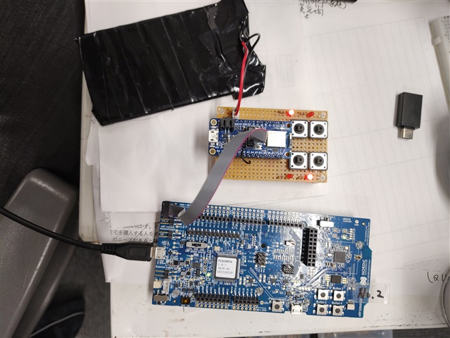
First of all, I have two "nrf52840-dk" and use "SEGGER Embedded Studio" to install the mesh sample "light_switch" (server) to the two "DKs" and use the Android app "nRF Mesh" I checked the operation and it worked fine.

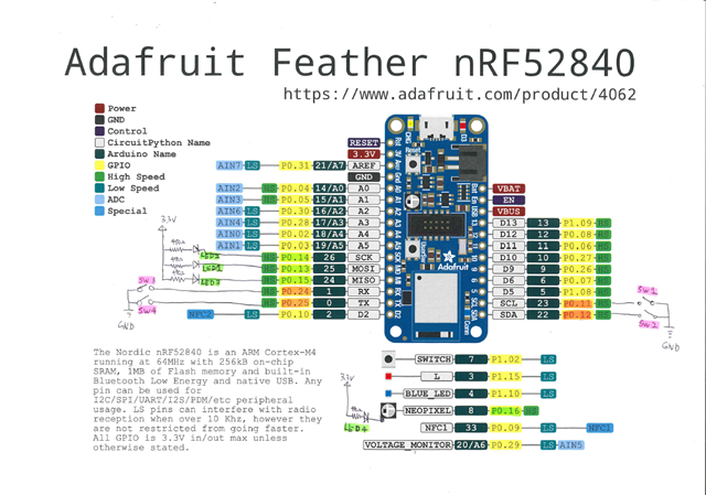
I wanted to build more networks here, so I built an Adafruit Feather nRF52840 Express with 4 switches and 4 LEDs just like the DK. And installed "light_switch" (server) via SWD.

But this didn't work the same as "DK".
Debug Terminal shows the following message:

<t: 0>, main.c, 367, ----- BLE Mesh Light Switch Server Demo -----
<t: 18925>, app_error_weak.c, 105, Mesh assert at 0x0002FC50 (:0)

Are these settings missing?
I have no idea.

  • Hi,

    For using nRF5 SDK (and nRF5 SDK for Mesh) projects on custom boards, you will need a board file for the custom board, in order for pin configurations to be correct. See Using the SDK with other boards for details.

    In addition, there might be differences in crystals, oscillators and power source for different boards. For instance, the nRF52840 Dongle needs different settings than the DK, and so for that Dongle we have the nRF52840 Dongle Programming Tutorial. What settings and steps are needed, depend on the particular board.

    Please note also that for new projects we recommend nRF Connect SDK, as nRF5 SDK is now in maintenance mode. See our nRF Connect SDK and nRF5 SDK statement for details. The Adafruit Feather nRF52840 Express seems to be supported already in nRF Connect SDK, through board files in the Zephyr Project. You could try out the Bluetooth: Mesh light sample in nRF Connect SDK, which corresponds to the light switch examples from nRF5 SDK for Mesh.

    Regards,
    Terje

  • If using the nRF5 SDK this code I wrote might be helpful in creating the required board-specific header file to put in /boards/:

    #define MAP(port, pin) (((port) << 5) | ((pin) & 0x1F))
    //                                                                           +------------------- Feather nRF52840 Board Assembly Pinout
    //                                                                           |   +--------------- Feather nRF52840 BLE Module Pinout
    //                                                                           |   |   +----------- Feather nRF52840 Arduino Pinout
    //                                                                           |   |   |    +------ Internal Nordic nRF52840 Pinout
    //                                                                           |   |   |    |
    //                                                                           |   |   |    |        +--I/O Port 'Q'-Quiet Signals Only
    //                                          Feather                          |   |   |    |        |
    //                                          Pin Id  Schematic Name         Pin Pin Pin  Pin  Name  |  Functions  Description
    //                                          ======= =====================  === === ==== ==== ===== =  ========== ======================
    #define PIN_XL1              MAP(0,  0) // " - X1   PIN_XL1",               -  17  X1   D2   P0.00 -  XL1        Crystal 32.768kHz In
    #define PIN_XL2              MAP(0,  1) // " - X2   PIN_XL2",               -  18  X2   F2   P0.01 -  XL2        Crystal 32.768kHz Out
    #define PIN_FEATHER_A4       MAP(0,  2) // " 9 A4   EPD_DC_PIN",            9  11  A4   A12  P0.02 -  AIN0       Analog input 0
    #define PIN_FEATHER_A5       MAP(0,  3) // "10 A5   EPD_CS_PIN",           10   9  A5   B13  P0.03 -  AIN1       Analog input 1
    #define PIN_FEATHER_A0       MAP(0,  4) // " 5 A0   -",                     5  20  A0   J1   P0.04 -  AIN2       Analog input 2
    #define PIN_FEATHER_A1       MAP(0,  5) // " 6 A1   -",                     6  21  A1   K2   P0.05 -  AIN3       Analog input 3
    #define PIN_FEATHER_D11      MAP(0,  6) // "23 D11  LED1_G",               23  22  D11  L1   P0.06 -             D11
    #define PIN_FEATHER_D6       MAP(0,  7) // "20 D6   PWM_OUTPUT_PIN_1",     20  23  D6   M2   P0.07 -  TRACECLK   Trace clk Trace clock
    #define PIN_FEATHER_D12      MAP(0,  8) // "24 D12  LED2_R",               24  24  D12  N1   P0.08 -             D12
    #define PIN_NFC1             MAP(0,  9) // " -  -   PIN_NFC1",              -   -   -   L24  P0.09 -  NFC1       NFC antenna
    #define PIN_NFC2             MAP(0, 10) // " -  -   PIN_NFC2",              -   -   -   J24  P0.10 -  NFC2       NFC antenna
    #define PIN_FEATHER_SCL      MAP(0, 11) // "18 SCL  -",                    18  27  SCL  T2   P0.11 -  TRACEDATA2 Trace 2           SCL
    #define PIN_FEATHER_SDA      MAP(0, 12) // "17 SDA  LED2_B",               17  29  SDA  U1   P0.12 -  TRACEDATA1 Trace 1
    #define PIN_FEATHER_MOSI     MAP(0, 13) // "12 MOSI SPIM_MOSI_PIN",        12  37  MOSI AD8  P0.13 -
    #define PIN_FEATHER_SCK      MAP(0, 14) // "11 SCK  SPIM_SCK_PIN",         11  36  SCK  AC9  P0.14 -
    #define PIN_FEATHER_MISO     MAP(0, 15) // "13 MISO -",                    13  39  MISO AD10 P0.15 -
    #define PIN_NEOPIXEL_RGB_LED MAP(0, 16) // " - NEO  PIN_NEOPIXEL_RGB_LED",  -  38  NEO  AC11 P0.16 -             NEOPIXEL RGB LED
    #define PIN_QSPI_FLASH_IO0   MAP(0, 17) // " - Q0   PIN_QSPI_FLASH_IO0",    -  41  Q0   AD12 P0.17 -             QSPI D0  GD25Q16 16MBit FLASH
    #define PIN_NRESET           MAP(0, 18) // " 1  -   PIN_NRESET",            1  40   -   AC13 P0.18 -  nRESET     nRESET
    #define PIN_QSPI_FLASH_SCK   MAP(0, 19) // " = QC   PIN_QSPI_FLASH_SCK",    =  42  QC   AC15 P0.19 -             QSPI SCK GD25Q16 16MBit FLASH
    #define PIN_QSPI_FLASH_CSN   MAP(0, 20) // " - QCS  PIN_QSPI_FLASH_CSN",    -  44  QCS  AD16 P0.20 -             QSPI CS  GD25Q16 16MBit FLASH
    #define PIN_QSPI_FLASH_IO3   MAP(0, 21) // " - Q3   PIN_QSPI_FLASH_IO3",    -  43  Q3   AC17 P0.21 -             QSPI D3  GD25Q16 16MBit FLASH
    #define PIN_QSPI_FLASH_IO1   MAP(0, 22) // " - Q1   PIN_QSPI_FLASH_IO1",    -  46  Q1   AD18 P0.22 -             QSPI D1  GD25Q16 16MBit FLASH
    #define PIN_QSPI_FLASH_IO2   MAP(0, 23) // " - Q2   PIN_QSPI_FLASH_IO2",    -  45  Q2   AC19 P0.23 -             QSPI D2  GD25Q16 16MBit FLASH
    #define PIN_FEATHER_RXD      MAP(0, 24) // "14 RXD  RX_PIN_NUMBER",        14  48  RXD  AD20 P0.24 -             RXD
    #define PIN_FEATHER_TXD      MAP(0, 25) // "15 TXD  TX_PIN_NUMBER",        15  49  TXD  AC21 P0.25 -             TXD
    #define PIN_FEATHER_D9       MAP(0, 26) // "21 D9   PWM_OUTPUT_PIN_0",     21  19  D9   G1   P0.26 -
    #define PIN_FEATHER_D10      MAP(0, 27) // "22 D10  -",                    22  16  D10  H2   P0.27 -
    #define PIN_FEATHER_A3       MAP(0, 28) // " 8 A3   EPD_RST_PIN",           8  13  A3   B11  P0.28 -  AIN4       Analog input 4
    #define PIN_VDIV             MAP(0, 29) // " = VDIV PIN_VDIV",              =  10  VDIV A10  P0.29 -  AIN5       Analog input 5
    #define PIN_FEATHER_A2       MAP(0, 30) // " 7 A2   EPD_BUSY_PIN",          7  14  A2   B9   P0.30 -  AIN6       Analog input 6
    #define PIN_FEATHER_AREF     MAP(0, 31) // " 3 AREF -",                     3  12  AREF A8   P0.31 -  AIN7/AREF  Analog input 7
    #define PIN_SWO              MAP(1,  0) // " - SWO  PIN_SWO",               -  47  SWO  AD22 P1.00 -  TRACEDATA0 Trace 0   SWO
    #define PIN_P1_01            MAP(1,  1) // " -  -   -",                     -   -   -   Y23  P1.01 Q
    #define PIN_SWITCH           MAP(1,  2) // " - SW   BUTTON_1",              -  50  SW   W24  P1.02 Q             SWITCH
    #define PIN_P1_03            MAP(1,  3) // " -  -   -",                    59  V23   -   -   P1.03 Q
    #define PIN_P1_04            MAP(1,  4) // " -  -   -",                    60  U24   -   -   P1.04 Q
    #define PIN_P1_05            MAP(1,  5) // " -  -   -",                    48  T23   -   -   P1.05 Q
    #define PIN_P1_06            MAP(1,  6) // " -  -   ",                     49  R24   -   -   P1.06 Q
    #define PIN_P1_07            MAP(1,  7) // " -  -   -",                    50  P23   -   -   P1.07 Q
    #define PIN_FEATHER_D5       MAP(1,  8) // "19 D5   ",                     51  P2   19  D5   P1.08 -
    #define PIN_FEATHER_D13      MAP(1,  9) // "25 D13  ",                     52  R1   25  D13  P1.09 -  TRACEDATA3 Trace 3
    #define PIN_LED2_BLUE        MAP(1, 10) // " - LED2 PIN_LED2_BLUE",        53  A20   -  LED2 P1.10 Q  Blue LED on board
    #define PIN_P1_11            vAP(1, 11) // " -  -   -",                    54  B19   -   -   P1.11 Q
    #define PIN_P1_12            MAP(1, 12) // " -  -   -",                    61  B17   -   -   P1.12 Q
    #define PIN_P1_13            MAP(1, 13) // " -  -   -",                    62  A16   -   -   P1.13 Q
    #define PIN_P1_14            MAP(1, 14) // " -  -   -",                    63  B15   -   -   P1.14 Q
    #define PIN_LED1_RED         MAP(1, 15) // " - LED1 PIN_LED1_RED"          64  A14   -  LED1 P1.15 Q  Red LED on board

Related