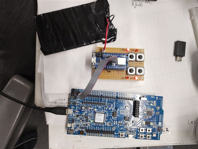
How to install mesh_sdk "light_switch" from "nrf52840-dk" to "Adafruit Feather nRF52840 Express".

First of all, I have two "nrf52840-dk" and use "SEGGER Embedded Studio" to install the mesh sample "light_switch" (server) to the two "DKs" and use the Android app "nRF Mesh" I checked the operation and it worked fine.

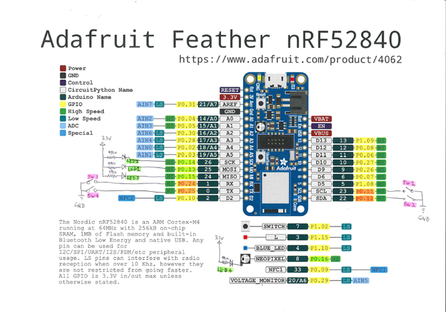
I wanted to build more networks here, so I built an Adafruit Feather nRF52840 Express with 4 switches and 4 LEDs just like the DK. And installed "light_switch" (server) via SWD.

But this didn't work the same as "DK".
Debug Terminal shows the following message:

<t: 0>, main.c, 367, ----- BLE Mesh Light Switch Server Demo -----
<t: 18925>, app_error_weak.c, 105, Mesh assert at 0x0002FC50 (:0)

Are these settings missing?
I have no idea.
Parents
  • If using the nRF5 SDK this code I wrote might be helpful in creating the required board-specific header file to put in /boards/:

    #define MAP(port, pin) (((port) << 5) | ((pin) & 0x1F))
    //                                                                           +------------------- Feather nRF52840 Board Assembly Pinout
    //                                                                           |   +--------------- Feather nRF52840 BLE Module Pinout
    //                                                                           |   |   +----------- Feather nRF52840 Arduino Pinout
    //                                                                           |   |   |    +------ Internal Nordic nRF52840 Pinout
    //                                                                           |   |   |    |
    //                                                                           |   |   |    |        +--I/O Port 'Q'-Quiet Signals Only
    //                                          Feather                          |   |   |    |        |
    //                                          Pin Id  Schematic Name         Pin Pin Pin  Pin  Name  |  Functions  Description
    //                                          ======= =====================  === === ==== ==== ===== =  ========== ======================
    #define PIN_XL1              MAP(0,  0) // " - X1   PIN_XL1",               -  17  X1   D2   P0.00 -  XL1        Crystal 32.768kHz In
    #define PIN_XL2              MAP(0,  1) // " - X2   PIN_XL2",               -  18  X2   F2   P0.01 -  XL2        Crystal 32.768kHz Out
    #define PIN_FEATHER_A4       MAP(0,  2) // " 9 A4   EPD_DC_PIN",            9  11  A4   A12  P0.02 -  AIN0       Analog input 0
    #define PIN_FEATHER_A5       MAP(0,  3) // "10 A5   EPD_CS_PIN",           10   9  A5   B13  P0.03 -  AIN1       Analog input 1
    #define PIN_FEATHER_A0       MAP(0,  4) // " 5 A0   -",                     5  20  A0   J1   P0.04 -  AIN2       Analog input 2
    #define PIN_FEATHER_A1       MAP(0,  5) // " 6 A1   -",                     6  21  A1   K2   P0.05 -  AIN3       Analog input 3
    #define PIN_FEATHER_D11      MAP(0,  6) // "23 D11  LED1_G",               23  22  D11  L1   P0.06 -             D11
    #define PIN_FEATHER_D6       MAP(0,  7) // "20 D6   PWM_OUTPUT_PIN_1",     20  23  D6   M2   P0.07 -  TRACECLK   Trace clk Trace clock
    #define PIN_FEATHER_D12      MAP(0,  8) // "24 D12  LED2_R",               24  24  D12  N1   P0.08 -             D12
    #define PIN_NFC1             MAP(0,  9) // " -  -   PIN_NFC1",              -   -   -   L24  P0.09 -  NFC1       NFC antenna
    #define PIN_NFC2             MAP(0, 10) // " -  -   PIN_NFC2",              -   -   -   J24  P0.10 -  NFC2       NFC antenna
    #define PIN_FEATHER_SCL      MAP(0, 11) // "18 SCL  -",                    18  27  SCL  T2   P0.11 -  TRACEDATA2 Trace 2           SCL
    #define PIN_FEATHER_SDA      MAP(0, 12) // "17 SDA  LED2_B",               17  29  SDA  U1   P0.12 -  TRACEDATA1 Trace 1
    #define PIN_FEATHER_MOSI     MAP(0, 13) // "12 MOSI SPIM_MOSI_PIN",        12  37  MOSI AD8  P0.13 -
    #define PIN_FEATHER_SCK      MAP(0, 14) // "11 SCK  SPIM_SCK_PIN",         11  36  SCK  AC9  P0.14 -
    #define PIN_FEATHER_MISO     MAP(0, 15) // "13 MISO -",                    13  39  MISO AD10 P0.15 -
    #define PIN_NEOPIXEL_RGB_LED MAP(0, 16) // " - NEO  PIN_NEOPIXEL_RGB_LED",  -  38  NEO  AC11 P0.16 -             NEOPIXEL RGB LED
    #define PIN_QSPI_FLASH_IO0   MAP(0, 17) // " - Q0   PIN_QSPI_FLASH_IO0",    -  41  Q0   AD12 P0.17 -             QSPI D0  GD25Q16 16MBit FLASH
    #define PIN_NRESET           MAP(0, 18) // " 1  -   PIN_NRESET",            1  40   -   AC13 P0.18 -  nRESET     nRESET
    #define PIN_QSPI_FLASH_SCK   MAP(0, 19) // " = QC   PIN_QSPI_FLASH_SCK",    =  42  QC   AC15 P0.19 -             QSPI SCK GD25Q16 16MBit FLASH
    #define PIN_QSPI_FLASH_CSN   MAP(0, 20) // " - QCS  PIN_QSPI_FLASH_CSN",    -  44  QCS  AD16 P0.20 -             QSPI CS  GD25Q16 16MBit FLASH
    #define PIN_QSPI_FLASH_IO3   MAP(0, 21) // " - Q3   PIN_QSPI_FLASH_IO3",    -  43  Q3   AC17 P0.21 -             QSPI D3  GD25Q16 16MBit FLASH
    #define PIN_QSPI_FLASH_IO1   MAP(0, 22) // " - Q1   PIN_QSPI_FLASH_IO1",    -  46  Q1   AD18 P0.22 -             QSPI D1  GD25Q16 16MBit FLASH
    #define PIN_QSPI_FLASH_IO2   MAP(0, 23) // " - Q2   PIN_QSPI_FLASH_IO2",    -  45  Q2   AC19 P0.23 -             QSPI D2  GD25Q16 16MBit FLASH
    #define PIN_FEATHER_RXD      MAP(0, 24) // "14 RXD  RX_PIN_NUMBER",        14  48  RXD  AD20 P0.24 -             RXD
    #define PIN_FEATHER_TXD      MAP(0, 25) // "15 TXD  TX_PIN_NUMBER",        15  49  TXD  AC21 P0.25 -             TXD
    #define PIN_FEATHER_D9       MAP(0, 26) // "21 D9   PWM_OUTPUT_PIN_0",     21  19  D9   G1   P0.26 -
    #define PIN_FEATHER_D10      MAP(0, 27) // "22 D10  -",                    22  16  D10  H2   P0.27 -
    #define PIN_FEATHER_A3       MAP(0, 28) // " 8 A3   EPD_RST_PIN",           8  13  A3   B11  P0.28 -  AIN4       Analog input 4
    #define PIN_VDIV             MAP(0, 29) // " = VDIV PIN_VDIV",              =  10  VDIV A10  P0.29 -  AIN5       Analog input 5
    #define PIN_FEATHER_A2       MAP(0, 30) // " 7 A2   EPD_BUSY_PIN",          7  14  A2   B9   P0.30 -  AIN6       Analog input 6
    #define PIN_FEATHER_AREF     MAP(0, 31) // " 3 AREF -",                     3  12  AREF A8   P0.31 -  AIN7/AREF  Analog input 7
    #define PIN_SWO              MAP(1,  0) // " - SWO  PIN_SWO",               -  47  SWO  AD22 P1.00 -  TRACEDATA0 Trace 0   SWO
    #define PIN_P1_01            MAP(1,  1) // " -  -   -",                     -   -   -   Y23  P1.01 Q
    #define PIN_SWITCH           MAP(1,  2) // " - SW   BUTTON_1",              -  50  SW   W24  P1.02 Q             SWITCH
    #define PIN_P1_03            MAP(1,  3) // " -  -   -",                    59  V23   -   -   P1.03 Q
    #define PIN_P1_04            MAP(1,  4) // " -  -   -",                    60  U24   -   -   P1.04 Q
    #define PIN_P1_05            MAP(1,  5) // " -  -   -",                    48  T23   -   -   P1.05 Q
    #define PIN_P1_06            MAP(1,  6) // " -  -   ",                     49  R24   -   -   P1.06 Q
    #define PIN_P1_07            MAP(1,  7) // " -  -   -",                    50  P23   -   -   P1.07 Q
    #define PIN_FEATHER_D5       MAP(1,  8) // "19 D5   ",                     51  P2   19  D5   P1.08 -
    #define PIN_FEATHER_D13      MAP(1,  9) // "25 D13  ",                     52  R1   25  D13  P1.09 -  TRACEDATA3 Trace 3
    #define PIN_LED2_BLUE        MAP(1, 10) // " - LED2 PIN_LED2_BLUE",        53  A20   -  LED2 P1.10 Q  Blue LED on board
    #define PIN_P1_11            vAP(1, 11) // " -  -   -",                    54  B19   -   -   P1.11 Q
    #define PIN_P1_12            MAP(1, 12) // " -  -   -",                    61  B17   -   -   P1.12 Q
    #define PIN_P1_13            MAP(1, 13) // " -  -   -",                    62  A16   -   -   P1.13 Q
    #define PIN_P1_14            MAP(1, 14) // " -  -   -",                    63  B15   -   -   P1.14 Q
    #define PIN_LED1_RED         MAP(1, 15) // " - LED1 PIN_LED1_RED"          64  A14   -  LED1 P1.15 Q  Red LED on board

Reply
  • If using the nRF5 SDK this code I wrote might be helpful in creating the required board-specific header file to put in /boards/:

    #define MAP(port, pin) (((port) << 5) | ((pin) & 0x1F))
    //                                                                           +------------------- Feather nRF52840 Board Assembly Pinout
    //                                                                           |   +--------------- Feather nRF52840 BLE Module Pinout
    //                                                                           |   |   +----------- Feather nRF52840 Arduino Pinout
    //                                                                           |   |   |    +------ Internal Nordic nRF52840 Pinout
    //                                                                           |   |   |    |
    //                                                                           |   |   |    |        +--I/O Port 'Q'-Quiet Signals Only
    //                                          Feather                          |   |   |    |        |
    //                                          Pin Id  Schematic Name         Pin Pin Pin  Pin  Name  |  Functions  Description
    //                                          ======= =====================  === === ==== ==== ===== =  ========== ======================
    #define PIN_XL1              MAP(0,  0) // " - X1   PIN_XL1",               -  17  X1   D2   P0.00 -  XL1        Crystal 32.768kHz In
    #define PIN_XL2              MAP(0,  1) // " - X2   PIN_XL2",               -  18  X2   F2   P0.01 -  XL2        Crystal 32.768kHz Out
    #define PIN_FEATHER_A4       MAP(0,  2) // " 9 A4   EPD_DC_PIN",            9  11  A4   A12  P0.02 -  AIN0       Analog input 0
    #define PIN_FEATHER_A5       MAP(0,  3) // "10 A5   EPD_CS_PIN",           10   9  A5   B13  P0.03 -  AIN1       Analog input 1
    #define PIN_FEATHER_A0       MAP(0,  4) // " 5 A0   -",                     5  20  A0   J1   P0.04 -  AIN2       Analog input 2
    #define PIN_FEATHER_A1       MAP(0,  5) // " 6 A1   -",                     6  21  A1   K2   P0.05 -  AIN3       Analog input 3
    #define PIN_FEATHER_D11      MAP(0,  6) // "23 D11  LED1_G",               23  22  D11  L1   P0.06 -             D11
    #define PIN_FEATHER_D6       MAP(0,  7) // "20 D6   PWM_OUTPUT_PIN_1",     20  23  D6   M2   P0.07 -  TRACECLK   Trace clk Trace clock
    #define PIN_FEATHER_D12      MAP(0,  8) // "24 D12  LED2_R",               24  24  D12  N1   P0.08 -             D12
    #define PIN_NFC1             MAP(0,  9) // " -  -   PIN_NFC1",              -   -   -   L24  P0.09 -  NFC1       NFC antenna
    #define PIN_NFC2             MAP(0, 10) // " -  -   PIN_NFC2",              -   -   -   J24  P0.10 -  NFC2       NFC antenna
    #define PIN_FEATHER_SCL      MAP(0, 11) // "18 SCL  -",                    18  27  SCL  T2   P0.11 -  TRACEDATA2 Trace 2           SCL
    #define PIN_FEATHER_SDA      MAP(0, 12) // "17 SDA  LED2_B",               17  29  SDA  U1   P0.12 -  TRACEDATA1 Trace 1
    #define PIN_FEATHER_MOSI     MAP(0, 13) // "12 MOSI SPIM_MOSI_PIN",        12  37  MOSI AD8  P0.13 -
    #define PIN_FEATHER_SCK      MAP(0, 14) // "11 SCK  SPIM_SCK_PIN",         11  36  SCK  AC9  P0.14 -
    #define PIN_FEATHER_MISO     MAP(0, 15) // "13 MISO -",                    13  39  MISO AD10 P0.15 -
    #define PIN_NEOPIXEL_RGB_LED MAP(0, 16) // " - NEO  PIN_NEOPIXEL_RGB_LED",  -  38  NEO  AC11 P0.16 -             NEOPIXEL RGB LED
    #define PIN_QSPI_FLASH_IO0   MAP(0, 17) // " - Q0   PIN_QSPI_FLASH_IO0",    -  41  Q0   AD12 P0.17 -             QSPI D0  GD25Q16 16MBit FLASH
    #define PIN_NRESET           MAP(0, 18) // " 1  -   PIN_NRESET",            1  40   -   AC13 P0.18 -  nRESET     nRESET
    #define PIN_QSPI_FLASH_SCK   MAP(0, 19) // " = QC   PIN_QSPI_FLASH_SCK",    =  42  QC   AC15 P0.19 -             QSPI SCK GD25Q16 16MBit FLASH
    #define PIN_QSPI_FLASH_CSN   MAP(0, 20) // " - QCS  PIN_QSPI_FLASH_CSN",    -  44  QCS  AD16 P0.20 -             QSPI CS  GD25Q16 16MBit FLASH
    #define PIN_QSPI_FLASH_IO3   MAP(0, 21) // " - Q3   PIN_QSPI_FLASH_IO3",    -  43  Q3   AC17 P0.21 -             QSPI D3  GD25Q16 16MBit FLASH
    #define PIN_QSPI_FLASH_IO1   MAP(0, 22) // " - Q1   PIN_QSPI_FLASH_IO1",    -  46  Q1   AD18 P0.22 -             QSPI D1  GD25Q16 16MBit FLASH
    #define PIN_QSPI_FLASH_IO2   MAP(0, 23) // " - Q2   PIN_QSPI_FLASH_IO2",    -  45  Q2   AC19 P0.23 -             QSPI D2  GD25Q16 16MBit FLASH
    #define PIN_FEATHER_RXD      MAP(0, 24) // "14 RXD  RX_PIN_NUMBER",        14  48  RXD  AD20 P0.24 -             RXD
    #define PIN_FEATHER_TXD      MAP(0, 25) // "15 TXD  TX_PIN_NUMBER",        15  49  TXD  AC21 P0.25 -             TXD
    #define PIN_FEATHER_D9       MAP(0, 26) // "21 D9   PWM_OUTPUT_PIN_0",     21  19  D9   G1   P0.26 -
    #define PIN_FEATHER_D10      MAP(0, 27) // "22 D10  -",                    22  16  D10  H2   P0.27 -
    #define PIN_FEATHER_A3       MAP(0, 28) // " 8 A3   EPD_RST_PIN",           8  13  A3   B11  P0.28 -  AIN4       Analog input 4
    #define PIN_VDIV             MAP(0, 29) // " = VDIV PIN_VDIV",              =  10  VDIV A10  P0.29 -  AIN5       Analog input 5
    #define PIN_FEATHER_A2       MAP(0, 30) // " 7 A2   EPD_BUSY_PIN",          7  14  A2   B9   P0.30 -  AIN6       Analog input 6
    #define PIN_FEATHER_AREF     MAP(0, 31) // " 3 AREF -",                     3  12  AREF A8   P0.31 -  AIN7/AREF  Analog input 7
    #define PIN_SWO              MAP(1,  0) // " - SWO  PIN_SWO",               -  47  SWO  AD22 P1.00 -  TRACEDATA0 Trace 0   SWO
    #define PIN_P1_01            MAP(1,  1) // " -  -   -",                     -   -   -   Y23  P1.01 Q
    #define PIN_SWITCH           MAP(1,  2) // " - SW   BUTTON_1",              -  50  SW   W24  P1.02 Q             SWITCH
    #define PIN_P1_03            MAP(1,  3) // " -  -   -",                    59  V23   -   -   P1.03 Q
    #define PIN_P1_04            MAP(1,  4) // " -  -   -",                    60  U24   -   -   P1.04 Q
    #define PIN_P1_05            MAP(1,  5) // " -  -   -",                    48  T23   -   -   P1.05 Q
    #define PIN_P1_06            MAP(1,  6) // " -  -   ",                     49  R24   -   -   P1.06 Q
    #define PIN_P1_07            MAP(1,  7) // " -  -   -",                    50  P23   -   -   P1.07 Q
    #define PIN_FEATHER_D5       MAP(1,  8) // "19 D5   ",                     51  P2   19  D5   P1.08 -
    #define PIN_FEATHER_D13      MAP(1,  9) // "25 D13  ",                     52  R1   25  D13  P1.09 -  TRACEDATA3 Trace 3
    #define PIN_LED2_BLUE        MAP(1, 10) // " - LED2 PIN_LED2_BLUE",        53  A20   -  LED2 P1.10 Q  Blue LED on board
    #define PIN_P1_11            vAP(1, 11) // " -  -   -",                    54  B19   -   -   P1.11 Q
    #define PIN_P1_12            MAP(1, 12) // " -  -   -",                    61  B17   -   -   P1.12 Q
    #define PIN_P1_13            MAP(1, 13) // " -  -   -",                    62  A16   -   -   P1.13 Q
    #define PIN_P1_14            MAP(1, 14) // " -  -   -",                    63  B15   -   -   P1.14 Q
    #define PIN_LED1_RED         MAP(1, 15) // " - LED1 PIN_LED1_RED"          64  A14   -  LED1 P1.15 Q  Red LED on board

Children
No Data
Related