I2S pins inconsistencies

Hello I am playing with Arduino / nrf52840 but I cannot seem to use I2S reliably.

On the first board, Seeed XIAO BLE Sense, the only pins that seem to work are 4, 5, 6. When I try a multisample (which requires double buffering) it outputs really poor audio.
On the second board, Adafruit ItsyBitsy Express, no pins seem to be outputting.

I am using this sample (replacing the main with setup): https://github.com/andenore/NordicSnippets/blob/master/examples/i2s_master/main.c

The DAC is a MAX98357A from Sparkfun: https://www.sparkfun.com/products/14809

Are there any nuances when using I2S? How can I debug what's going on?
The DAC works fine when connected to a different MCU board.

  • Hi,

    We do not support Arduino directly, so for anything Arduino specific you may be better off in some Arduino forum. The low-level code you refer to should be the same regardless though, but it should also work the same on any nRF52840 board, so I wonder what your HW looks like? Are these pins you use available? Or are they connected to some external circuitry that cause problems?

  • Thank you Einar.
    I agree with you with the part "low level code should work the same", I mean I am literally setting values in HW registers and that is what makes the mystery intriguing.
    The hardware is pretty simple, I am using the two dev boards as they are.

    This is the pin out for the ItsyBitsy. Notice that pin 4 and 6 are not available. Notice also Adafruit claims any pin (GPIO I assume) works with I2S.

    This is the pin out for the Xiao BLE Sense.

    -enzo

    OK, oscilloscope response on the boards.
    When I choose pins (4,5,6) (OUT, SCLK, LRCLK), everything works fine, oscilloscope confirms.
    When I choose pins (5,7,9) - or any other quiet combination - the oscilloscope shows all the 3 pins toggling with LRCLK frequency. 

    I wonder if this code requires some form of mapping? I can see some signal appearing on different pins.

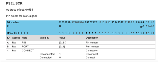
    NRF_I2S->PSEL.SCK = (PIN_SCK << I2S_PSEL_SCK_PIN_Pos);
    NRF_I2S->PSEL.LRCK = (PIN_LRCK << I2S_PSEL_LRCK_PIN_Pos);
    NRF_I2S->PSEL.SDOUT = (PIN_SDOUT << I2S_PSEL_SDOUT_PIN_Pos);

    Open mouth

    Argh. It's not the logical pin number, but the physical one which explains... a lot!

  • Hi,

    Yes, you are right. All pin assignments are with reference to GPIO pin number (which for the nRF52840 consists of port and number, and for port 1 that in practice just means adding 32). You can see the mapping between GPIO pin number and pin on the package for different package variants under Pin assignments in the product specification.

Related