I2S pins inconsistencies

Hello I am playing with Arduino / nrf52840 but I cannot seem to use I2S reliably.

On the first board, Seeed XIAO BLE Sense, the only pins that seem to work are 4, 5, 6. When I try a multisample (which requires double buffering) it outputs really poor audio.
On the second board, Adafruit ItsyBitsy Express, no pins seem to be outputting.

I am using this sample (replacing the main with setup): https://github.com/andenore/NordicSnippets/blob/master/examples/i2s_master/main.c

The DAC is a MAX98357A from Sparkfun: https://www.sparkfun.com/products/14809

Are there any nuances when using I2S? How can I debug what's going on?
The DAC works fine when connected to a different MCU board.

Parents
  • Hi,

    We do not support Arduino directly, so for anything Arduino specific you may be better off in some Arduino forum. The low-level code you refer to should be the same regardless though, but it should also work the same on any nRF52840 board, so I wonder what your HW looks like? Are these pins you use available? Or are they connected to some external circuitry that cause problems?

  • Thank you Einar.
    I agree with you with the part "low level code should work the same", I mean I am literally setting values in HW registers and that is what makes the mystery intriguing.
    The hardware is pretty simple, I am using the two dev boards as they are.

    This is the pin out for the ItsyBitsy. Notice that pin 4 and 6 are not available. Notice also Adafruit claims any pin (GPIO I assume) works with I2S.

    This is the pin out for the Xiao BLE Sense.

    -enzo

    OK, oscilloscope response on the boards.
    When I choose pins (4,5,6) (OUT, SCLK, LRCLK), everything works fine, oscilloscope confirms.
    When I choose pins (5,7,9) - or any other quiet combination - the oscilloscope shows all the 3 pins toggling with LRCLK frequency. 

    I wonder if this code requires some form of mapping? I can see some signal appearing on different pins.

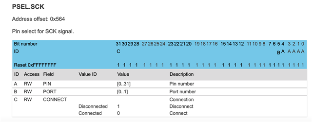
    NRF_I2S->PSEL.SCK = (PIN_SCK << I2S_PSEL_SCK_PIN_Pos);
    NRF_I2S->PSEL.LRCK = (PIN_LRCK << I2S_PSEL_LRCK_PIN_Pos);
    NRF_I2S->PSEL.SDOUT = (PIN_SDOUT << I2S_PSEL_SDOUT_PIN_Pos);

    Open mouth

    Argh. It's not the logical pin number, but the physical one which explains... a lot!

Reply
  • Thank you Einar.
    I agree with you with the part "low level code should work the same", I mean I am literally setting values in HW registers and that is what makes the mystery intriguing.
    The hardware is pretty simple, I am using the two dev boards as they are.

    This is the pin out for the ItsyBitsy. Notice that pin 4 and 6 are not available. Notice also Adafruit claims any pin (GPIO I assume) works with I2S.

    This is the pin out for the Xiao BLE Sense.

    -enzo

    OK, oscilloscope response on the boards.
    When I choose pins (4,5,6) (OUT, SCLK, LRCLK), everything works fine, oscilloscope confirms.
    When I choose pins (5,7,9) - or any other quiet combination - the oscilloscope shows all the 3 pins toggling with LRCLK frequency. 

    I wonder if this code requires some form of mapping? I can see some signal appearing on different pins.

    NRF_I2S->PSEL.SCK = (PIN_SCK << I2S_PSEL_SCK_PIN_Pos);
    NRF_I2S->PSEL.LRCK = (PIN_LRCK << I2S_PSEL_LRCK_PIN_Pos);
    NRF_I2S->PSEL.SDOUT = (PIN_SDOUT << I2S_PSEL_SDOUT_PIN_Pos);

    Open mouth

    Argh. It's not the logical pin number, but the physical one which explains... a lot!

Children
Related