NRF24LE1

Hello, first of all, I am an engineering student. I want to learn communication and I just started it. I don't understand exactly what the following lines do. How can I do? What are the current resources? I couldn't understand the following lines of code.... Waiting for your support. ((The codes are completely taken from (enhanced_shockburst_ptx_nrf24le1.uvproj))

What part of the code does the actual work? Where is the ACK part? I don't want ACK and I want to work at 1 Mbps.

I don't know about addressing either, I don't know where to start :)

Thank you from now...

Parents
  • Hi

    I don't know what you mean by the "actual work"? 

    In the nRF24LE1 the radio core handles the ESB protocol for you, all the application has to do is to write to the configuration registers, write a payload, and raise the CE line for 10 microseconds to initiate a transfer. Essentially the nRF24LE1 is just the nRF24L01+ radio chip and an 8-bit MCU bundled together on the same chip, and if you read the datasheet of the nRF24L01+ and the nRF24LE1 you will see that the radio works more or less identically. 

    The NRF_ISR interrupt is triggered every time the radio raises its interrupt line, and this can happen either as a result of a successfully transmitted packet (TX_DS), a failed transmission (MAX_RT) or a reception of a packet (RX_DR). 

    All the code to the right is doing is to write a new TX payload over the internal SPI bus, raise the CE line for 10 microseconds to start the transmission, and wait for the operation to complete by waiting for the radio_busy flag to be cleared by the interrupt handler. 

    In order to disable ACK it should be sufficient to open your pipe with the auto_ack flag cleared using the hal_nrf_open_pipe function (this has to be done both on the TX and RX side):

    hal_nrf_open_pipe(HAL_NRF_PIPE0, false);

    The address in the radio has two primary purposes. On one hand it serves as a sync word, and allows the receiver to detect the start of a valid packet over the air. Secondly it allows different devices operating in the same area to coexist by having them use different addresses, so that a packet sent by one device will not be picked up by the wrong receiver. 

    Exactly what you set the address to is less important, just be aware that addresses with very few bit shifts are more challenging for the receiver to pick up and could lead to higher packet loss. 

    Best regards
    Torbjørn

  • ESB

    thank you

    What should I do to run at 1 mbps? How are address definitions made? Are there any sample codes for these?

  • I can communicate by entering the address on the TX and without touching the RX, but when I enter the address on the RX, I cannot communicate. I don't know where I am doing wrong, can you help me? Thanks

    It's the first time I've dealt with the address, I'm sorry I may have a lot of mistakes.

  • Hi 

    You mean to say you changed the address on the TX side only and it still works? 

    That sounds odd. You need to have the same address configured on both sides for communication to work. 

    Possibly you are not sending on the same pipe that you configured the address for? 

    Could you zip the source files for your TX and RX applications so I can have a look at the code? 

    Best regards
    Torbjørn

  • I've been trying for days, I still can't understand the problem. were you able to look?

  • /* Copyright (c) 2009 Nordic Semiconductor. All Rights Reserved.
    *
    * The information contained herein is property of Nordic Semiconductor ASA.
    * Terms and conditions of usage are described in detail in NORDIC
    * SEMICONDUCTOR STANDARD SOFTWARE LICENSE AGREEMENT.
    *
    * Licensees are granted free, non-transferable use of the information. NO
    * WARRENTY of ANY KIND is provided. This heading must NOT be removed from
    * the file.
    *
    * $LastChangedRevision: 2513 $

    */

    /** @file
    * @brief Enhanced ShockBurst Primary Transmitter example
    * @defgroup esb_ptx_example Enhanced ShockBurst Primary Transmitter (PTX) example
    * @{
    * @ingroup nrf_examples
    *
    * @brief This example sends packets continuously. The contents of P0 are
    * sent in the first payload byte (byte 0).
    *
    * The example shows the minimum required setup for transmitting packets to a
    * primary receiver (PRX) device.
    *
    * The following default radio parameters are being used:
    * - RF channel 2
    * - 2 Mbps data rate
    * - TX address 0xE7E7E7E7E7
    * - 1 byte CRC
    *
    * The project @ref esb_prx_example can be used as a counterpart for receiving the data.

    *
    */

    //lint -e717
    //lint -e714
    //lint -e640

    #ifdef MCU_NRF24LE1
    #include "nrf24le1.h"
    #include "hal_clk.h"
    #endif


    #include <stdint.h>
    #include <stdbool.h>
    #include "hal_nrf.h"


    // Global variables
    static bool volatile radio_busy;
    uint8_t address[5]={0xB3,0xB4,0xB5,0xB6,0xF2};

    void main(void)
    {
    uint8_t payload[3];

    #ifdef MCU_NRF24LE1
    while(hal_clk_get_16m_source() != HAL_CLK_XOSC16M)
    {
    // Wait until 16 MHz crystal oscillator is running
    }
    #endif


    // Enable the radio clock
    RFCKEN = 1U;

    // Enable RF interrupt
    RF = 1U;

    // Enable global interrupt
    EA = 1U;
    hal_nrf_set_operation_mode(HAL_NRF_PTX);
    hal_nrf_set_address_width(HAL_NRF_AW_5BYTES); // 5 bytes address width
    hal_nrf_set_address(HAL_NRF_PIPE0, address); // Set device's addresses

    // Power up radio
    hal_nrf_set_power_mode(HAL_NRF_PWR_UP);

    for(;;)
    {
    // Put P0 contents in payload[0]
    payload[0] = P0;

    // Write payload to radio TX FIFO
    hal_nrf_write_tx_payload(payload, 3U);

    // Toggle radio CE signal to start transmission
    CE_PULSE();

    radio_busy = true;
    // Wait for radio operation to finish
    while (radio_busy)

    {
    }
    }
    }

    // Radio interrupt
    NRF_ISR()
    {
    uint8_t irq_flags;

    // Read and clear IRQ flags from radio
    irq_flags = hal_nrf_get_clear_irq_flags();

    switch(irq_flags)
    {
    // Transmission success
    case (1 << (uint8_t)HAL_NRF_TX_DS):
    radio_busy = false;
    // Data has been sent
    break;
    // Transmission failed (maximum re-transmits)
    case (1 << (uint8_t)HAL_NRF_MAX_RT):
    // When a MAX_RT interrupt occurs the TX payload will not be removed from the TX FIFO.
    // If the packet is to be discarded this must be done manually by flushing the TX FIFO.
    // Alternatively, CE_PULSE() can be called re-starting transmission of the payload.
    // (Will only be possible after the radio irq flags are cleared)
    hal_nrf_flush_tx();
    radio_busy = false;
    break;
    default:
    break;

    }
    }
    /** @} */

Reply
  • /* Copyright (c) 2009 Nordic Semiconductor. All Rights Reserved.
    *
    * The information contained herein is property of Nordic Semiconductor ASA.
    * Terms and conditions of usage are described in detail in NORDIC
    * SEMICONDUCTOR STANDARD SOFTWARE LICENSE AGREEMENT.
    *
    * Licensees are granted free, non-transferable use of the information. NO
    * WARRENTY of ANY KIND is provided. This heading must NOT be removed from
    * the file.
    *
    * $LastChangedRevision: 2513 $

    */

    /** @file
    * @brief Enhanced ShockBurst Primary Transmitter example
    * @defgroup esb_ptx_example Enhanced ShockBurst Primary Transmitter (PTX) example
    * @{
    * @ingroup nrf_examples
    *
    * @brief This example sends packets continuously. The contents of P0 are
    * sent in the first payload byte (byte 0).
    *
    * The example shows the minimum required setup for transmitting packets to a
    * primary receiver (PRX) device.
    *
    * The following default radio parameters are being used:
    * - RF channel 2
    * - 2 Mbps data rate
    * - TX address 0xE7E7E7E7E7
    * - 1 byte CRC
    *
    * The project @ref esb_prx_example can be used as a counterpart for receiving the data.

    *
    */

    //lint -e717
    //lint -e714
    //lint -e640

    #ifdef MCU_NRF24LE1
    #include "nrf24le1.h"
    #include "hal_clk.h"
    #endif


    #include <stdint.h>
    #include <stdbool.h>
    #include "hal_nrf.h"


    // Global variables
    static bool volatile radio_busy;
    uint8_t address[5]={0xB3,0xB4,0xB5,0xB6,0xF2};

    void main(void)
    {
    uint8_t payload[3];

    #ifdef MCU_NRF24LE1
    while(hal_clk_get_16m_source() != HAL_CLK_XOSC16M)
    {
    // Wait until 16 MHz crystal oscillator is running
    }
    #endif


    // Enable the radio clock
    RFCKEN = 1U;

    // Enable RF interrupt
    RF = 1U;

    // Enable global interrupt
    EA = 1U;
    hal_nrf_set_operation_mode(HAL_NRF_PTX);
    hal_nrf_set_address_width(HAL_NRF_AW_5BYTES); // 5 bytes address width
    hal_nrf_set_address(HAL_NRF_PIPE0, address); // Set device's addresses

    // Power up radio
    hal_nrf_set_power_mode(HAL_NRF_PWR_UP);

    for(;;)
    {
    // Put P0 contents in payload[0]
    payload[0] = P0;

    // Write payload to radio TX FIFO
    hal_nrf_write_tx_payload(payload, 3U);

    // Toggle radio CE signal to start transmission
    CE_PULSE();

    radio_busy = true;
    // Wait for radio operation to finish
    while (radio_busy)

    {
    }
    }
    }

    // Radio interrupt
    NRF_ISR()
    {
    uint8_t irq_flags;

    // Read and clear IRQ flags from radio
    irq_flags = hal_nrf_get_clear_irq_flags();

    switch(irq_flags)
    {
    // Transmission success
    case (1 << (uint8_t)HAL_NRF_TX_DS):
    radio_busy = false;
    // Data has been sent
    break;
    // Transmission failed (maximum re-transmits)
    case (1 << (uint8_t)HAL_NRF_MAX_RT):
    // When a MAX_RT interrupt occurs the TX payload will not be removed from the TX FIFO.
    // If the packet is to be discarded this must be done manually by flushing the TX FIFO.
    // Alternatively, CE_PULSE() can be called re-starting transmission of the payload.
    // (Will only be possible after the radio irq flags are cleared)
    hal_nrf_flush_tx();
    radio_busy = false;
    break;
    default:
    break;

    }
    }
    /** @} */

Children
  • /* Copyright (c) 2009 Nordic Semiconductor. All Rights Reserved.
    *
    * The information contained herein is confidential property of Nordic
    * Semiconductor ASA.Terms and conditions of usage are described in detail
    * in NORDIC SEMICONDUCTOR STANDARD SOFTWARE LICENSE AGREEMENT.
    *
    * Licensees are granted free, non-transferable use of the information. NO
    * WARRENTY of ANY KIND is provided. This heading must NOT be removed from
    * the file.
    *
    * $LastChangedRevision: 2211 $

    */

    /** @file
    * @brief Enhanced ShockBurst Primary Receiver example
    * @defgroup esb_prx_example Enhanced ShockBurst Primary Receiver (PRX) example
    * @{
    * @ingroup nrf_examples
    *
    * @brief This example monitors for data and writes the first byte (byte 0) of the
    * received payloads to P0.
    *
    * The example shows the minimum required setup for receiving packets from a
    * primary transmitter (PTX) device.
    *
    * The following default radio parameters are being used:
    * - RF channel 2
    * - 2 Mbps data rate
    * - RX address 0xE7E7E7E7E7 (pipe 0) and 0xC2C2C2C2C2 (pipe 1)
    * - 1 byte CRC
    *
    * The project @ref esb_ptx_example can be used as a counterpart for transmitting the data.

    *
    */

    //lint -e717
    //lint -e534
    //lint -e714
    //lint -e783

    #ifdef MCU_NRF24LE1
    #include "nrf24le1.h"
    #include "hal_clk.h"
    #endif

    #ifdef MCU_NRF24LU1P
    #include "nrf24lu1p.h"
    #endif

    #include <stdint.h>
    #include "hal_nrf.h"

    // Global variables
    uint8_t payload[3];
    uint8_t address[5]={0xB3,0xB4,0xB5,0xB6,0xF2};
    void main()
    {
    #ifdef MCU_NRF24LE1
    while(hal_clk_get_16m_source() != HAL_CLK_XOSC16M)
    {
    // Wait until 16 MHz crystal oscillator is running
    }
    #endif

    #ifdef MCU_NRF24LU1P
    // Enable radio SPI
    RFCTL = 0x10;
    #endif

    // Set P0 as output
    P0DIR = 0;

    // Enable the radio clock
    RFCKEN = 1;

    // Enable RF interrupt
    RF = 1;
    // Enable global interrupt
    EA = 1;

    hal_nrf_set_address_width(HAL_NRF_AW_5BYTES); // 5 bytes address width
    hal_nrf_set_address(HAL_NRF_PIPE0, address); // Set device's addresses

    Radyoyu birincil alıcı (PRX) hal_nrf_set_operation_mode(HAL_NRF_PRX)
    olarak yapılandırma;

    Yük genişliğini 3 bayta ayarlayın
    hal_nrf_set_rx_payload_width((int)HAL_NRF_PIPE0, 3);

    Radyo
    hal_nrf_set_power_mode (HAL_NRF_PWR_UP) açın;

    Alıcı
    CE_HIGH();

    için(;;) {}
    }

    Radyo kesme
    NRF_ISR()
    {
    uint8_t irq_flags;

    IRQ bayraklarını radyo
    irq_flags okuma ve temizleme = hal_nrf_get_clear_irq_flags();

    if data
    ((irq_flags & (1<<(uint8_t))HAL_NRF_RX_DR)) > 0) { /
    / Read payload while(!hal_nrf_rx_fifo_empty())

    {
    hal_nrf_read_rx_payload(payload
    );

    }

    Alınan yükü[0] bağlantı noktasına 0
    P0 = payload[0] yazın;

    }
    }
    /** @} */

  • Hi

    I can't really see any obvious errors in the code that would explain this behavior. I would have to try to test this myself, and unfortunately I don't have any LE1 kits available at the moment. I will try to get some time to test this by the end of the week (please note we are working limited hours over christmas). 

    In the mean time can you give me a bit more information about how you are testing this? 

    Are you simply using the nRF24LE1 development kits, pushing buttons on one side and looking for LED updates on the other side?

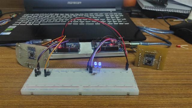
    If you are not using standard Nordic devkits, could you send me a picture of your setup?

    Best regards
    Torbjørn

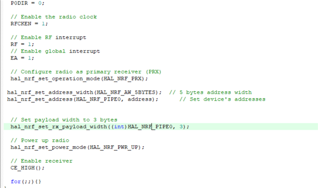
  • Hello, first of all, thank you. I have read the codes many times but I don't know. Normally the receiver should not receive data from different addresses, but my receiver does. I leave my schematic, codes and more. thanks 

  • Hi

    I dug out my old nRF24LE1 kits and tested the standard examples, with some code added to simulate your changes (like the modified address). 

    One thing I realized is that in order to properly update the address you need to set both the TX and the PIPE0 address on the PTX side, otherwise the transmission won't work properly. 

    The PTX will essentially send the packet using the TX address, and look for the ACK on the PIPE0 address, so in order to have successful communication with ACK you need to set these two addresses identically. 

    Could you try to make this change and see if it works better?

    If needed I have attached my main files below:

    /* Copyright (c) 2009 Nordic Semiconductor. All Rights Reserved.
     *
     * The information contained herein is property of Nordic Semiconductor ASA.
     * Terms and conditions of usage are described in detail in NORDIC
     * SEMICONDUCTOR STANDARD SOFTWARE LICENSE AGREEMENT.
     *
     * Licensees are granted free, non-transferable use of the information. NO
     * WARRENTY of ANY KIND is provided. This heading must NOT be removed from
     * the file.
     *
     * $LastChangedRevision: 2513 $
     */
    
    /** @file
     * @brief Enhanced ShockBurst Primary Transmitter example
     * @defgroup esb_ptx_example Enhanced ShockBurst Primary Transmitter (PTX) example
     * @{
     * @ingroup nrf_examples
     *
     * @brief This example sends packets continuously. The contents of P0 are
     * sent in the first payload byte (byte 0).
     *
     * The example shows the minimum required setup for transmitting packets to a
     * primary receiver (PRX) device.
     *
     * The following default radio parameters are being used:
     * - RF channel 2
     * - 2 Mbps data rate
     * - TX address 0xE7E7E7E7E7
     * - 1 byte CRC
     *
     * The project @ref esb_prx_example can be used as a counterpart for receiving the data.
     *
    */
    
    //lint -e717
    //lint -e714
    //lint -e640
    
    #ifdef MCU_NRF24LE1
    #include "nrf24le1.h"
    #include "hal_clk.h"
    #endif
    
    #ifdef MCU_NRF24LU1P
    #include "nrf24lu1p.h"
    #endif
    
    #include <stdint.h>
    #include <stdbool.h>
    #include "hal_nrf.h"
    #ifndef MCU_NRF24LU1P
    #include "hal_clk.h" //lint !e322 !e7 "include file not found"
    #endif
    
    // Global variables
    static bool volatile radio_busy;
    
    uint8_t address[5]={0xB3,0xB4,0xB5,0xB6,0xF2};
    
    void main(void)
    {
      uint8_t payload[3];
    
      #ifdef MCU_NRF24LE1
      while(hal_clk_get_16m_source() != HAL_CLK_XOSC16M)
      {
        // Wait until 16 MHz crystal oscillator is running
      }
      #endif
    
      #ifdef MCU_NRF24LU1P
      // Enable radio SPI
      RFCTL = 0x10U;
      #endif
    
      // Enable the radio clock
      RFCKEN = 1U;
    
      // Enable RF interrupt
      RF = 1U;
    
      // Enable global interrupt
      EA = 1U;
    
      hal_nrf_set_address_width(HAL_NRF_AW_5BYTES); // 5 bytes address width
      hal_nrf_set_address(HAL_NRF_PIPE0, address); // Set device's addresses
      hal_nrf_set_address(HAL_NRF_TX, address); // Set device's addresses
      
      // Power up radio
      hal_nrf_set_power_mode(HAL_NRF_PWR_UP);
    
      for(;;)
      {
        // Put P0 contents in payload[0]
        payload[0] = ~P0;
    
        // Write payload to radio TX FIFO
        hal_nrf_write_tx_payload(payload, 3U);
    
        // Toggle radio CE signal to start transmission
        CE_PULSE();
    
        radio_busy = true;
        // Wait for radio operation to finish
        while (radio_busy)
        {
        }
      }
    }
    
    // Radio interrupt
    NRF_ISR()
    {
      uint8_t irq_flags;
    
      // Read and clear IRQ flags from radio
      irq_flags = hal_nrf_get_clear_irq_flags();
    
      switch(irq_flags)
      {
        // Transmission success
        case (1 << (uint8_t)HAL_NRF_TX_DS):
          radio_busy = false;
          // Data has been sent
          break;
        // Transmission failed (maximum re-transmits)
        case (1 << (uint8_t)HAL_NRF_MAX_RT):
          // When a MAX_RT interrupt occurs the TX payload will not be removed from the TX FIFO.
          // If the packet is to be discarded this must be done manually by flushing the TX FIFO.
          // Alternatively, CE_PULSE() can be called re-starting transmission of the payload.
          // (Will only be possible after the radio irq flags are cleared)
          hal_nrf_flush_tx();
          radio_busy = false;
          break;
        default:
          break;
      }
    }
    /** @} */
    
    /* Copyright (c) 2009 Nordic Semiconductor. All Rights Reserved.
     *
     * The information contained herein is confidential property of Nordic
     * Semiconductor ASA.Terms and conditions of usage are described in detail
     * in NORDIC SEMICONDUCTOR STANDARD SOFTWARE LICENSE AGREEMENT.
     *
     * Licensees are granted free, non-transferable use of the information. NO
     * WARRENTY of ANY KIND is provided. This heading must NOT be removed from
     * the file.
     *
     * $LastChangedRevision: 2211 $
     */
    
    /** @file
     * @brief Enhanced ShockBurst Primary Receiver example
     * @defgroup esb_prx_example Enhanced ShockBurst Primary Receiver (PRX) example
     * @{
     * @ingroup nrf_examples
     *
     * @brief This example monitors for data and writes the first byte (byte 0) of the
     * received payloads to P0.
     *
     * The example shows the minimum required setup for receiving packets from a
     * primary transmitter (PTX) device.
     *
     * The following default radio parameters are being used:
     * - RF channel 2
     * - 2 Mbps data rate
     * - RX address 0xE7E7E7E7E7 (pipe 0) and 0xC2C2C2C2C2 (pipe 1)
     * - 1 byte CRC
     *
     * The project @ref esb_ptx_example can be used as a counterpart for transmitting the data.
     *
    */
    
    //lint -e717
    //lint -e534
    //lint -e714
    //lint -e783
    
    #ifdef MCU_NRF24LE1
    #include "nrf24le1.h"
    #include "hal_clk.h"
    #endif
    
    #ifdef MCU_NRF24LU1P
    #include "nrf24lu1p.h"
    #endif
    
    #include <stdint.h>
    #include "hal_nrf.h"
    
    // Global variables
    uint8_t payload[3];
    
    uint8_t address[5]={0xB3,0xB4,0xB5,0xB6,0xF2};
    
    void main()
    {
    #ifdef MCU_NRF24LE1
      while(hal_clk_get_16m_source() != HAL_CLK_XOSC16M)
      {
        // Wait until 16 MHz crystal oscillator is running
      }
    #endif
      
      #ifdef MCU_NRF24LU1P
      // Enable radio SPI
      RFCTL = 0x10;
      #endif
    
      // Set P0 as output
      P0DIR = 0;
    
      // Enable the radio clock
      RFCKEN = 1;
    
      // Enable RF interrupt
      RF = 1;
      // Enable global interrupt
      EA = 1;
    
      // Configure radio as primary receiver (PTX)
      hal_nrf_set_operation_mode(HAL_NRF_PRX);
    
      // Set payload width to 3 bytes
      hal_nrf_set_rx_payload_width((int)HAL_NRF_PIPE0, 3);
      
      hal_nrf_set_address_width(HAL_NRF_AW_5BYTES); // 5 bytes address width
      hal_nrf_set_address(HAL_NRF_PIPE0, address); // Set device's addresses
    
      // Power up radio
      hal_nrf_set_power_mode(HAL_NRF_PWR_UP);
    
      // Enable receiver
      CE_HIGH();
    
      for(;;){}
    }
    
    // Radio interrupt
    NRF_ISR()
    {
      uint8_t irq_flags;
    
      // Read and clear IRQ flags from radio
      irq_flags = hal_nrf_get_clear_irq_flags();
    
      // If data received
      if((irq_flags & (1<<(uint8_t)HAL_NRF_RX_DR)) > 0)
      {
        // Read payload
        while(!hal_nrf_rx_fifo_empty())
        {
          hal_nrf_read_rx_payload(payload);
        }
    
        // Write received payload[0] to port 0
        P0 = payload[0];
      }
    }
    /** @} */
    

    Best regards
    Torbjørn

Related