PWM not working after upgrade to nrf Connect SDK 1.9.1

Since upgrading to nrf Connect SDK 1.9.1, I no longer have PWM output. No errors returned when calling pwm_pin_set_usec, yet no output.

I tried upgrading to the latest nrf Connect SDK (2.2.0), thinking that perhaps a bug was fixed, but the number of changes (include paths, etc) was too daunting.

Parents
  • Hi,

    Can you post the part of your code where you use pwm_pin_set_usec()?

    Regards,
    Sigurd Hellesvik

  • #define AFE_CLOCK_NODE  DT_ALIAS(afe_clock)

    #if DT_NODE_HAS_STATUS(AFE_CLOCK_NODE, okay)
    #ifndef DT_PWMS_LABEL
    #define AFE_CLOCK_LABEL DT_NODELABEL(AFE_CLOCK_NODE)
    #else
    #define AFE_CLOCK_LABEL DT_PWMS_LABEL(AFE_CLOCK_NODE)
    #endif
    #define AFE_CLOCK_CHANNEL   DT_PWMS_CHANNEL(AFE_CLOCK_NODE)
    #define AFE_CLOCK_FLAGS DT_PWMS_FLAGS(AFE_CLOCK_NODE)
    #else
    #error "Unsupported board: afe-clock devicetree alias is not defined"
    #define AFE_CLOCK_LABEL ""
    #define AFE_CLOCK_CHANNEL   0
    #define AFE_CLOCK_FLAGS 0
    #endif
     
        int ret = 0;

        _AfeClock_dev = device_get_binding(AFE_CLOCK_LABEL);
        if (!_AfeClock_dev) {
            Z_LOG(LOG_LEVEL_ERR, "Error: didn't find %s device.", AFE_CLOCK_LABEL);
            ret |= 0x1;
        }
     
        retpwm_pin_set_usec(AfeClock_dev, AFE_CLOCK_CHANNEL,
                       PWM_USEC(period), PWM_USEC(width), AFE_CLOCK_FLAGS);
        if (ret) {
            Z_LOG(LOG_LEVEL_ERR, "Error %d: failed to set pulse width.", ret);
        }
  • I need to change all the clock modes, comment out most of the other pin definitions, and change enough of the code that if it doesn’t work I’d be unsure whether something I did wrong made it stop working. Not impossible, just difficult. I will take a look at the latest fade_led example and update my code to match the DTS definitions and code for manipulating the PWM properties. Hopefully that will shed some light. 

  • I was able to convert my device tree and software calls to be consistent with latest best practices. I am now able to get my PWM signal out! Unfortunately, my SPI communication has now stopped as the polarity of the CS signal is inverted. I am guessing that it is a similar issue with device tree and software calls. Should I create a new ticket or address it here? My old code grabbed the device object from the device tree and then I defined a spi_config struct to pass on the spi_read/write/transceive calls. Since this seems to not be working, I updated to defining the CS parameters in the device tree itself and am using the spi_read_dt/write_dt/transceive_dt calls but it still won't change the polarity of the CS signal. I need ACTIVE_LOW. I am using spi1. Any insights?

  • csteaderman said:
    I am now able to get my PWM signal out!

    Good to hear!

    csteaderman said:
    Should I create a new ticket or address it here?

    We can continue here.

    csteaderman said:
    Any insights?

    Can you share your pinctrl configuration for SPI?

    Our central nRF pairing sample uses SPI with ACTIVE LOW cs-gpios.
    Is this what you need?

    Regards,
    Sigurd Hellesvik

  • Here are the relevant sections from the pinctrl file and device tree files.

    	spi1_default: spi1_default {
    		group1 {
    			psels = <NRF_PSEL(SPIM_SCK, 0, 16)>,
    				<NRF_PSEL(SPIM_MOSI, 0, 15)>,
    				<NRF_PSEL(SPIM_MISO, 0, 14)>;
    		};
    	};
    
    	spi1_sleep: spi1_sleep {
    		group1 {
    			psels = <NRF_PSEL(SPIM_SCK, 0, 16)>,
    				<NRF_PSEL(SPIM_MOSI, 0, 15)>,
    				<NRF_PSEL(SPIM_MISO, 0, 14)>;
    			low-power-enable;
    		};
    	};

    &spi1 {
    	compatible = "nordic,nrf-spi";
    	status = "okay";
    	pinctrl-0 = <&spi1_default>;
    	pinctrl-1 = <&spi1_sleep>;
    	pinctrl-names = "default", "sleep";
    	cs-gpios = <&gpio0 18 GPIO_ACTIVE_LOW>;
    	afe4490: afe4490@0 {
    		compatible = "vnd,spi-device";
    		reg = <0>;
    		spi-max-frequency = <4000000>;
    		label = "afe4490";
    	};
    };
    

  • Can you share your SPI code?

    Or even better, a minimal sample with only SPI communication so I can try to replicate the issue on my end?

    Regards,
    Sigurd Hellesvik

Reply Children
  • Here is my SPI code. I have tested both the non-dts and the dts version of the functions, both perform the same with the CS being inverted.

    /* spi.c - SPI wrapper */
    
    #include <stdint.h>
    #include <zephyr/device.h>
    #include <zephyr/drivers/spi.h>
    #include "spi.h"
    
    #include <zephyr/logging/log.h>
    LOG_MODULE_REGISTER(spi_wrapper, CONFIG_LOG_DEFAULT_LEVEL);
    
    static struct spi_buf rx;
    const static struct spi_buf_set rx_bufs = {
    	.buffers = &rx,
    	.count = 1,
    };
    
    static struct spi_buf tx;
    const static struct spi_buf_set tx_bufs = {
    	.buffers = &tx,
    	.count = 1,
    };
    
    static const struct spi_config spi_cfg = {
    	.operation = SPI_OP_MODE_MASTER | SPI_WORD_SET(8) | SPI_TRANSFER_MSB,
    	.frequency = 4000000,
    	.slave = 0,
        .cs = &(struct spi_cs_control) {
            .delay = 1,
            .gpio.pin = 18,
            .gpio.dt_flags = GPIO_ACTIVE_LOW,
            .gpio.port = DEVICE_DT_GET(DT_NODELABEL(gpio0)),
        },
    };
    
    int spi_send(const struct device *spi,
            const uint8_t *data, size_t len)
    {
        tx.buf = (void*)data;
        tx.len = len;
    
    	return spi_write(spi, &spi_cfg, &tx_bufs);
    }
    
    int spi_send_dt(const struct spi_dt_spec *spi_dt,
        const uint8_t *data, size_t len)
    {
        tx.buf = (void*)data;
        tx.len = len;
    
    	return spi_write_dt(spi_dt, &tx_bufs);
    }
    
    int spi_recv(const struct device *spi,
        uint8_t *data, size_t len)
    {
        rx.buf = data;
        rx.len = len;
    
    	return spi_read(spi, &spi_cfg, &rx_bufs);
    }
    
    int spi_sendrecv(const struct device *spi,
        const uint8_t *writedata, uint8_t *readdata,
        size_t len)
    {
        tx.buf = (void*)writedata;
        tx.len = len;
        rx.buf = readdata;
        rx.len = len;
    
    	return spi_transceive(spi, &spi_cfg, &tx_bufs, &rx_bufs);
    }
    
    int spi_sendrecv_dt(const struct spi_dt_spec *spi_dt,
        const uint8_t *writedata, uint8_t *readdata,
        size_t len)
    {
        tx.buf = (void*)writedata;
        tx.len = len;
        rx.buf = readdata;
        rx.len = len;
    
    	return spi_transceive_dt(spi_dt, &tx_bufs, &rx_bufs);
    }
    

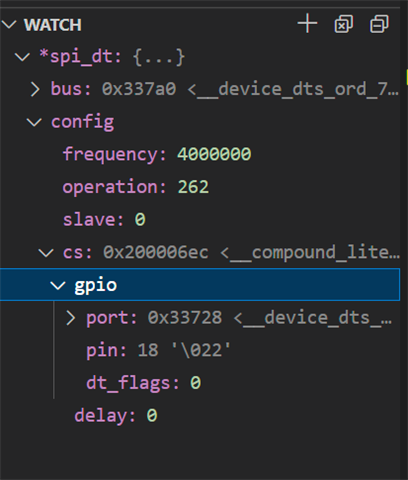
  • Some additional data. I think that my configuration of the DTS is correct. If I breakpoint in my SPI code at line 50 above, I can watch the spi_dt variable. If I set the cs-gpios to GPIO_ACTIVE_HIGH, I get the following:

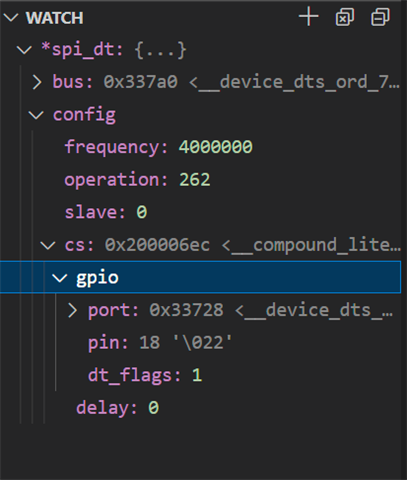
    If I set the cs_gpios to GPIO_ACTIVE_LOW, I get the following:

    So, I think that I am properly setting up the device tree, it just seems that the code that is supposed to interpret the dt_flags field is not honoring it when configuring the chip select. This is quite frustrating since I am so close to getting my device to work, but this one thing makes it completely useless.

  • Hi,

    csteaderman said:
    So, I think that I am properly setting up the device tree,

    I agree; it looks like the devicetree is

    A colleague of mine has an NCS-SPI-Master-Slave-Example.

    In this sample,  it looks like he has to get the GPIO configuration manually from the devicetree to use for his SPI functions:

    It looks like you are creating spi_cfg manually in your code posted below.
    But you set the CS pin to ACTIVE_LOW in your code manually as well, so I would think this should be enough hmm.

    So to test if ACTIVE_HIGH/ACTIVE_LOW works, I took the NCS-SPI-Master-Slave-Example sample.
    I built it for nRF Connect SDK v2.2.0 and ran it on an nRF52840DK.

    Then I change the CS Pin to LED3:

    diff --git a/nrf52840dk_nrf52840.overlay b/nrf52840dk_nrf52840.overlay
    index 84cbaaa..a3addf7 100644
    --- a/nrf52840dk_nrf52840.overlay
    +++ b/nrf52840dk_nrf52840.overlay
    @@ -41,7 +41,7 @@ my_spi_master: &spi1 {
            status = "okay";
            pinctrl-0 = <&spi1_default>;
            pinctrl-1 = <&spi1_sleep>;
    -       cs-gpios = <&gpio0 28 GPIO_ACTIVE_LOW>;
    +       cs-gpios = <&gpio0 15 GPIO_ACTIVE_LOW>;^M
            reg_my_spi_master: spi-dev-a@0 {
                    reg = <0>;
            };
    @@ -53,4 +53,4 @@ my_spi_slave: &spi2 {
            pinctrl-0 = <&spi2_default>;
            pinctrl-1 = <&spi2_sleep>;
            def-char = <0x00>;
    -};
    \ No newline at end of file
    

    I observe that LED3 is off.

    Then I change the CS pin to ACTIVE_HIGH:

    diff --git a/nrf52840dk_nrf52840.overlay b/nrf52840dk_nrf52840.overlay
    index 84cbaaa..9633808 100644
    --- a/nrf52840dk_nrf52840.overlay
    +++ b/nrf52840dk_nrf52840.overlay
    @@ -41,7 +41,7 @@ my_spi_master: &spi1 {
            status = "okay";
            pinctrl-0 = <&spi1_default>;
            pinctrl-1 = <&spi1_sleep>;
    -       cs-gpios = <&gpio0 28 GPIO_ACTIVE_LOW>;
    +       cs-gpios = <&gpio0 15 GPIO_ACTIVE_HIGH>;^M
            reg_my_spi_master: spi-dev-a@0 {
                    reg = <0>;
            };
    @@ -53,4 +53,4 @@ my_spi_slave: &spi2 {
            pinctrl-0 = <&spi2_default>;
            pinctrl-1 = <&spi2_sleep>;
            def-char = <0x00>;
    

    When I rebuild and flash this time, I observe that LED3 is on.

    From this, it looks like the CS pin ACTIVE_HIGH configuration works for this sample.

    Was this helpful?

    Regards,
    Sigurd Hellesvik

Related