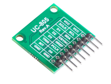
I am attempting to connect the Arducam hm01b0 to the nRF52840-DK embedded board, utilizing bare metal programming. The sensor comes with the following pins for serial interface. To access 4-bit interface( D1,D2,D3 and D4), the user has to solder the pins. However I am trying to get the HM01B0 working over the 1-bit interface and try to capture an image.

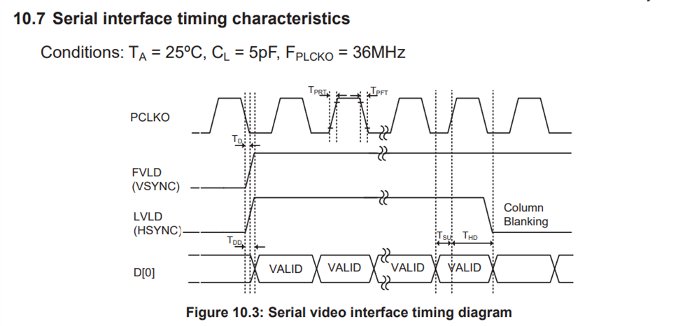
I am able to read and write to the sensor registers over I2C. The datasheet presents the following timings characteristics to capture an image.

I have connected the logic analyzer and I am able to see the corresponding waveform that is the data is being streamed over D0 line.

For 1 bit interface,the image sensor has a frame rate of 30 FPS and the frequency of PCLK is 36 Mhz. I know that GPIO pins would not be able to read the input signals in this
frequency range but I don't know how else to read a serial line. One option is making the image sensor as SPIM master and nrf52840 as SPIM slave. The image sensor provides the clock over PCLK which can be configured as SPI clock and the line D0 can be configured as MOSI line. However to read valid data bits/bytes over the serial line, VSYNC and HSYNC should also be read and made sure that their value is according to the serial video interface timings diagram. So I tried to read the serial line D0 by configuring it as a GPIO pin and I read 0x00 always.
How can I configure the image sensor and capture an image?
This is the code I have written,
// array to hold a complete frame
uint8_t  frameBuffer[324][324];

#define PIN_VSYNC      (28)
#define PIN_HSYNC      (29)
#define PIN_PCLK       (30)
#define PIN_D0         (31)

// initialise the pins of sensor
void hm0360_init()
{
    // GPIO I/P
    nrf_gpio_cfg_input(PIN_VSYNC, NRF_GPIO_PIN_PULLUP);
    nrf_gpio_cfg_input(PIN_HSYNC, NRF_GPIO_PIN_PULLUP);
    nrf_gpio_cfg_input(PIN_PCLK, NRF_GPIO_PIN_PULLUP);

    // GPIO O/P
     nrf_gpio_cfg_input(PIN_D0,NRF_GPIO_PIN_PULLUP);


    for(int i = 0; i < 324 ; i++){
        for(int j = 0; j < 324 ; j++){
            frameBuffer[i][j] = 0;
        }
     }
}


void hm01b0_read_frame_bits()
{
   int VSYNC_count = -1, HREF_count = 0;
   int incomingBits;
    unsigned char byte = 0;
    int byteArrayIndex = 0;
    int bitCount = 0;

while(nrf_gpio_pin_read(PIN_VSYNC) == LOW) { }
while(nrf_gpio_pin_read(PIN_VSYNC) == HIGH)
{
	while(nrf_gpio_pin_read(PIN_HSYNC) == false && nrf_gpio_pin_read(PIN_VSYNC) == HIGH) { }
    VSYNC_count++;
	HREF_count = 0;
	//Read a row
	while(nrf_gpio_pin_read(PIN_HSYNC) == true)
	{
		while(nrf_gpio_pin_read(PIN_PCLK) == false) { }
		// read 0 always
		incomingBits = nrf_gpio_pin_read(PIN_D0);
		byte = (byte << 1) | incomingBits;
		bitCount++;

		if (bitCount == 8) {
			frameBuffer[VSYNC_count][HREF_count++] = byte;
			bitCount = 0;
			byte = 0;
		}

		if (VSYNC_count == 324) {
			break;
		}

		while(nrf_gpio_pin_read(PIN_PCLK) == true) { }
	}

}

}
You can find the datasheet of the image sensor here : www.uctronics.com/.../HM01B0-MWA-image-sensor-datasheet.pdf


