This post is older than 2 years and might not be relevant anymore
More Info: Consider searching for newer posts

nRF51822 2 Layer Layout

I have been looking at the nRF51822 for a project, and have looked at several designs available on the web for reference (I prefer to plagiarize working stuff rather than invent new errors myself.) When comparing the Nordic layout recommendations and the layout of the BBC Micro:Bit I am wondering just how much leeway there is in working with the part. Looking at the Micro:Bit
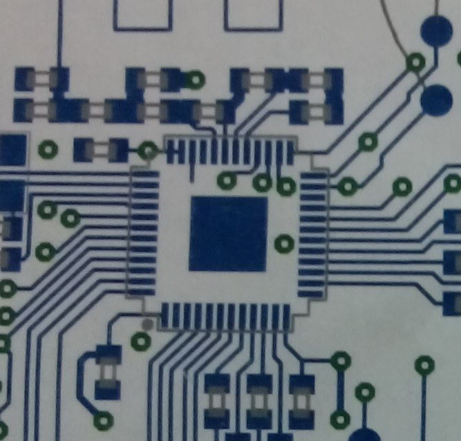
image description

I see they have shrunk the center pad considerably, routed signals under the part, used very long power feeds and violated a couple other "rules." The press releases indicate Nordic worked very closely on the design, so I was hoping to get some insight on the real design rules and / or feedback on the design practices used.

Cheers

Mike

  • Be sure to double check you aren't viewing the Paste Mask Layer instead of the Solder Mask Layer. Paste Mask layer will likely have a smaller center pad.

  • This is obviously a combined plot, but the copper layer is definitely one of the elements as traces and vias are shown. There is clearly routing and vias where the part's bottom pad should be.

  • Sorry didn't mean to click answer.

    Yes the copper layer is there since there are traces. Still can't tell the size of the Solder Mask opening nor the paste mask. It is likely fine as long as there is a solid contact to the Ground pad. The only real difference between the a smaller one like the one in the photo and the recommended size is thermal relief if i'm not mistaken. Once the connecting pad-size gets large enough.

  • Hi.

    Have you seen our reference layout files? We strongly recommend "plagiarizing" these layouts. You might also be interested in this blog post: General PCB design guidelines for nRF51

    EDIT: Answers to questions in comment below:

    I guess you are right in that the reference files don't really provide any context. The blogpost however, is a set of general recommendations which hasn't changed since february.

    When using the words "lie at the heart" I think our marketing department was merely pointing out that our chip is the main component used in the kit. Although we followed the design process closely it is not our design. When reviewing layouts we at Nordic mainly focus on the nRF and the components in its immediate surrounds and we felt comfortable endorsing BBC's design. As a side note: I guess you found the image posted in your initial post here, but note that the design shown in the blog is not the final one.

    I cannot in good conscience say that Nordic's recommendations in our blogs or reference designs are "rules made to be broken". Especially not on a public forum. But of course, you are rarely able to design electronics without doing some compromising. You will probably need to bend the rules a bit here and there, but our reference designs are proven to work and if you have to bend the rules that is on you. However, please feel free to submit your design on our MyPage support portal and we will be happy to do a review of it. We can also do tuning of the antenna and matching network. We strive to give you an answer within 24 hours and your questions and/or designs are handled with complete confidentiality.

    I don't think any of the recommendations you mention is overly restrictive or ambitious. As i mentioned, they are just general recommendations and you are of course free to use your own discretion.

    1. The ground plane is important for several reasons. E.g counterweight for the antenna (a small ground plane makes the antenna less efficient), return path for noise, and shielding of the RF part (under the matching network). Try to route as many traces as possible on the top layer to get a ground plane as coherent as possible on the bottom layer.

    2. Lots of vias are imortant. On large ground planes we recommend a via every 0.5-1.0 cm. Any local ground planes should be connected with several vias.

    3. A star network, with a center close to the power supply or a large capacitor, should be used to route the supply voltage to the nRF and other components on the board. Good filtering and decoupling is important as noise on the nRF's Vdd pins can be modulated into the carrier

    4. Again, it is a general rule of thumb. If not possible then maybe you can add a large capacitor close to the nRF.

    5. Nordic does not generally recommend routing any signals under the nRF (on any layer), but rather fill the area with a ground plane. As you can see, BBC chose to do it differently, which is their prerogative.

  • I am sorry, the reference layout files you link to provide no insight to your layout requirements but are merely Gerber files - lacking any context. It is possible that in the months since the blog post was made the design practices have changed. I am trying to understand your layout requirements in light of your more recent design.

    Nordic is trying very hard to be identified with the design I posted; to use your words "We, Nordic, lie at the heart of the the BBC micro:bit." so when a design is posted which I assume got a level of technical support from you that I could only dream of I think it is fair to ask questions about how the design decisions were made.

    So - specific questions:

    1. Your layout guideline blog states "A typical design consists of two ground planes; a top ground plane and a bottom ground plane. Both ground planes should preferably be as large and solid as possible." Is this recommendation overly restrictive?
    2. Your layout guideline blog states "The two ground planes should be connected using a lot of via holes." Is this recommendation overly ambitious?
    3. Your datasheet layout states "A PCB with a minimum of two layers, including a ground plane, is recommended" Is this recommendation overly restrictive?
    4. Your datasheet layout states "The supply voltage for the chip should be filtered and routed separately from the supply voltages of any digital circuitry" Is this recommendation overly restrictive?
    5. Your datasheet layout states "Long power supply lines on the PCB should be avoided." Is this recommendation overly restrictive?
    6. IPC recommends a copper attachment area nearly identical to the bottom conductor of a generic QFN, does Nordic recommend using a smaller copper area for its and routing signals below the nRF51822?

    If Nordic really believes the Micro:Bit is and instructional vehicle to "‘mainstreaming’ electronics design" I would like to know if Nordic endorses the design practices it used.

Related