NRF52810 Power Issue (SPI )

I do have different issue with Nrf52810. I am trying to build a wearable device with NRF52810 and LSM6DSMTR.
I am measuring the current towards the NRF52810 using a series resistor (100E).

Rectangle part is SPI Communication (NrF Delay) in the graph

Whenever I send an SPI command, I can see there is a triangle based current consumption (Not sure what it is ). 
You can see the image without SPI as well.

I am using SES V5.62 (SDK 7.2.0) 

Parents
  • Hi, can you try with a lower value series resistor, and check if you see the same thing? 100 Ohm is quite large, and you will get a significant voltage drop when the current increases. Maybe try with 10Ohm maximum.

    Is the LSM6DSMTR powered from the same power source? I.e. does it have the same voltage level? Are you able to measure the voltage on the MISO pin (and any other input pins you might have) and see if it is at a stable voltage during the triangular shaped period, and not floating up and down?

  • I have checked all the ways. Its not an issue associated with the sensor.  
    I also connected a AS6212 temperature sensor to the same chip using I2C lines. 

    Noticed same kind of issue there also. But When  I commented //twi_init(); &  //twi_deinit(); from teh call function issue resolved.
    So I hardly believe this is something with the SPI lines.


    float AS6212_read_temp(void)
    {
    
      float temperature_c = 0.0;
      bool singleSt = 0;
     
      //twi_init();
    
      nrf_drv_twi_enable(&m_twi);
    
      triggerSingleShotConversion();// enabling sleep mode
    
      nrf_delay_ms(AS6212_CONVERSION_TIME); //conversion ongoing
    
      for(char i=0; i<10; i++)
      {
        singleSt = getSingleShotStatus(); 
        if(!singleSt) {break;}
        else
        {
         NRF_LOG_INFO("AS6212 Conversion Not completed"); 
         nrf_delay_ms(5);
        }
      }
    
      temperature_c = readTempC();
    
    
      nrf_drv_twi_disable(&m_twi);  
      //twi_deinit();
    
      return temperature_c;
    }

  • Are you able to plot the voltage on the TWI lines, and at the same time plot the current? The reason I'm asking all these questions is that this is typical for floating GPIOs, i.e. the input buffer is connected internally, but it is not connected to anything externally. It could be other GPIOs as well, which are unintentionally left as floating inputs. For example the UART. The UART us used for logging by default in nordic examples, and the RX pin must be driven to a logic 1 while not in use, unless you can see current similar to your plots. This is also very unpredictable, so external changes may trigger this issue, like when you added the additional TWI lines.

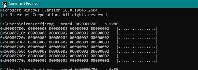
    Can you run this command and check the status of all GPIOs? Then please post the output here. Thanks

    nrfjprog --memrd 0x50000700 --n 0x80
  • When you are saying measure the voltage and current for the TWI lines, hope you are referring SPI lines (SCK, MOSI, MISO, CS)

  • Hi Stian,
    Can you advice on this. Thanks in Advance.

  • Hello

    Vijil Jose said:
    When you are saying measure the voltage and current for the TWI lines, hope you are referring SPI lines (SCK, MOSI, MISO, CS)

    I'm just referring to the pins you are using in your design. You said this:

    Vijil Jose said:
    Noticed same kind of issue there also. But When  I commented //twi_init(); &  //twi_deinit(); from teh call function issue resolved.
    So I hardly believe this is something with the SPI lines.

    So my apologies if you are using SPI only, and comment the TWI functions. If that is the case, the only pin I am worried about is pin 12. Can you try to pull this high (or low) while measuring current, and see if you have the same problem?

Reply
  • Hello

    Vijil Jose said:
    When you are saying measure the voltage and current for the TWI lines, hope you are referring SPI lines (SCK, MOSI, MISO, CS)

    I'm just referring to the pins you are using in your design. You said this:

    Vijil Jose said:
    Noticed same kind of issue there also. But When  I commented //twi_init(); &  //twi_deinit(); from teh call function issue resolved.
    So I hardly believe this is something with the SPI lines.

    So my apologies if you are using SPI only, and comment the TWI functions. If that is the case, the only pin I am worried about is pin 12. Can you try to pull this high (or low) while measuring current, and see if you have the same problem?

Children
Related