Hi Good Day,
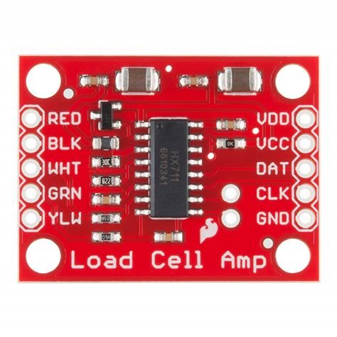
Please I am fairly new to the nRF framework and I am facing some problems with a project I am working on. I am trying to interface a load sensor with an nRF9160 using an HX711.
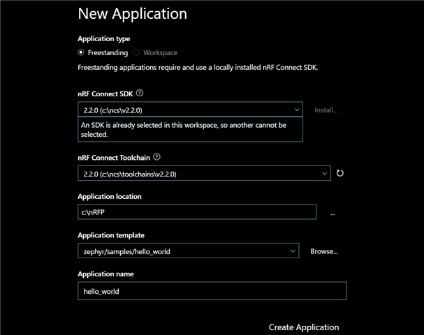
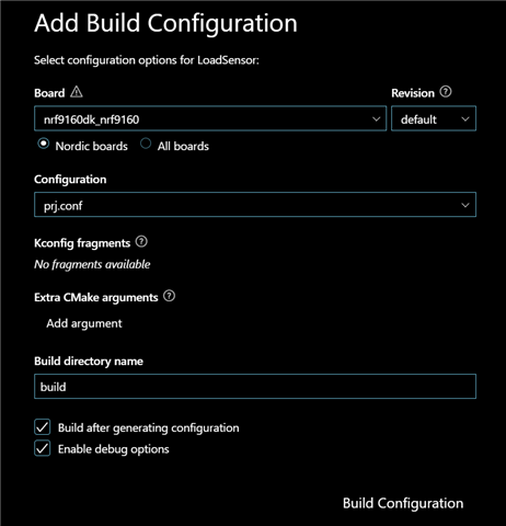
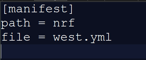
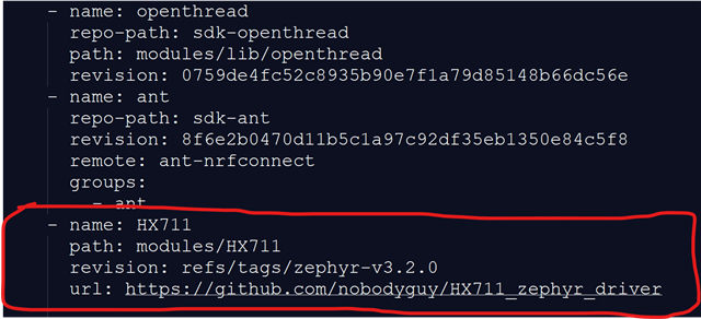
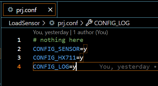
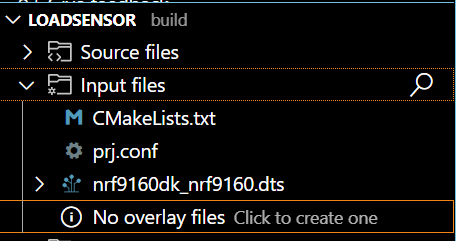
I have a hard time getting values from my load sensor using an HX711. I did some research and saw that there was a repo by nobody guy that gave some documentation on the installation, configuration and use of the HX711 library. So I followed the instructions and everything was installed and compiled successfully.
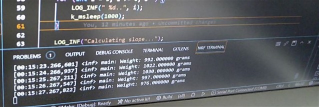
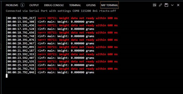
Problems arise when I connect my load sensors and HX711 with my microcontroller (nRF9160). I keep getting a zero value, even when weight is put on the load sensor. You can see this in the image below.
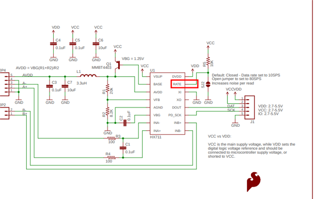
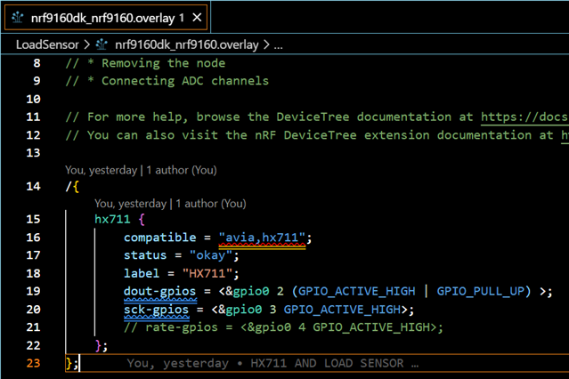
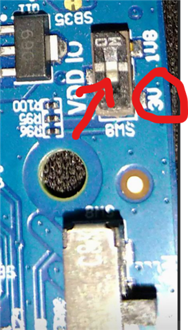
I am guessing my problems may be coming from my connections. But I don't really know exactly where to start checking. Also, I see that in this code, there are 3 data pins (SCK Dout and rate) and it confuses me a little, cause I am used to working with just 2 data pins when using the HX711 and load sensors.

Will this code affect me if I use a load sensor with just 2 data pins? How may I go about this?
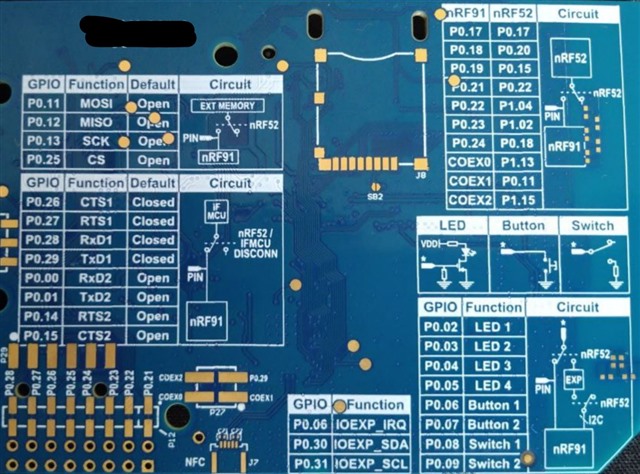
And finally, just to be sure, when a pin is declared as "gpio0 26" for example, does it mean we are using the physical pin labelled as "P0.26" for connection on the nRF board?
Any help would be much appreciated.
Thanks.