

hello Nordic
i am working with nrf52832 with ncs v1.9.2 with zephyr
i am using spim to read from a sensor
the spi xfer command is done via ppi with a timer ~20kHz
there is another timer set raise a gpiote, also via ppi, that tells the sensor start measure, also at the same speed.
the spi_done callback calles on a handler that pull the sensor gpiote back down, before it is raised back for the next conversion, and copy the data from the spi buffer.
the problem i see with a picoscop is that the spi_done callback takes to much time to happen (more then 46microsec after an 8 bytes data read spi_xfer is called (spi_tx is 0 bytes) ) . this does not happen all the time (and not on all of the boards). this really mess things up as the handler may be called while next spi_xfer is in process and by that trying to copy the buffers that are being used by the spi, off course we also loos a sample because the sensor gpiote was not pulled down and back up because the ppi task to raise the gpiote did nothing for the already raised gpiote.
this is a photo from the picoscop catch:
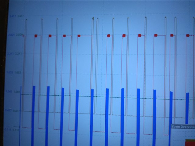
line color is brown for enter and exit the spi_done event handler
blue line is the spi clk and the
red line is the sensore start measure indication gpiote
this is the event handler code:
void ads8866_spi_done_event_handler(void *ctx, uint8_t *rx_buff, int size)
{
    const struct device                   *ads8866_chain = (const struct device *)ctx;
    const struct ads8866_chain_dev_config *cfg = ads8866_chain->config;
    struct ads8866_chain_data             *drv_data = ads8866_chain->data;
    static int                             run_idx = 0;

    gpio_pin_set(gpio_dev_red, 25, 1);

    nrfx_gpiote_clr_task_trigger(cfg->conv_gpio.pin);

#ifdef CONFIG_ADS8866_CHAIN_ACC_CHANNELS_CONNECTED
    vib0_arrays[fill_sample_buff_idx][run_idx] = 0x8000 ^ (uint16_t)(((uint16_t)(rx_buff[0]) << 8) | rx_buff[1]);
    vib1_arrays[fill_sample_buff_idx][run_idx] = 0x8000 ^ (uint16_t)(((uint16_t)(rx_buff[2]) << 8) | rx_buff[3]);
    vib2_arrays[fill_sample_buff_idx][run_idx] = 0x8000 ^ (uint16_t)(((uint16_t)(rx_buff[4]) << 8) | rx_buff[5]);
    mag_arrays[fill_sample_buff_idx][run_idx] = 0x8000 ^ (uint16_t)(((uint16_t)(rx_buff[6]) << 8) | rx_buff[7]);
#else
    mag_arrays[fill_sample_buff_idx][run_idx] = 0x8000 ^ (uint16_t)(((uint16_t)rx_buff[0] << 8) | rx_buff[1]);
#endif

    run_idx++;
    if (SAMPLE_BUFF_SIZE <= run_idx)
    {
        run_idx = 0;
        if (true == app_buff_busy)
        {
            buff_overrun = true;
            return;
        }
        int temp_idx = app_used_buff_idx;
        app_used_buff_idx = fill_sample_buff_idx;
        fill_sample_buff_idx = temp_idx;
        app_buff_busy = true;
        k_sem_give(&drv_data->thread_sem);
    }
    gpio_pin_set(gpio_dev_red, 25, 0);
}
this is the dts part of the sensor with the spi
&spi1 {
	status = "okay";
	sck-pin = <8>;    // gpio 0 pin 8
	mosi-pin = <0xFF>;
	miso-pin = <7>;    // gpio 0 pin 7
	compatible = "nordic,nrf-spim";
	ads8866_chain@0 {
		compatible = "ti,ads8866_chain";
		reg = <0>;
		chain_length = <4>;
		def_sample_freq = <20833>;
		conv_gpios = <&gpio0 6 GPIO_ACTIVE_HIGH>;
		str_gpios = <&gpio0 9 (GPIO_ACTIVE_HIGH | GPIO_PULL_DOWN)>;
		stbr_gpios = <&gpio0 10 (GPIO_ACTIVE_HIGH | GPIO_PULL_DOWN)>;
		label = "ADS8866_CHAIN";
		pm_mag_en_gpios = <&gpio0 22 GPIO_ACTIVE_HIGH>;
		pm_5v_en_gpios = <&gpio0 31 GPIO_ACTIVE_HIGH>;
		spi-max-frequency = <8000000>;
	};
};

&spi2 {
	status = "okay";
	sck-pin = <5>; // gpio 0 pin 5
	mosi-pin = <4>; // gpio 0 pin 4
	miso-pin = <2>; // gpio 0 pin 2
	compatible = "nordic,nrf-spim";
	cs-gpios = <&gpio0 3 (GPIO_PULL_UP | GPIO_ACTIVE_LOW)>;
	augu_flash_is25lp128: augu_flash_is25lp128@0 {
		compatible = "issi,augu_flash_is25lp128";
		reg = <0>;
		label = "AUGU_FLASH_IS25LP128";
		jedec_id = [ 9d 60 18  ];
		spi-max-frequency = <8000000>; //<133000000>;
		page_size = <256>;
		block_size = <65536>;
		size = <0x8000000>;
	};
};
any idea what can cause this delay ?
how can i check what is causing this delay, as it is supposed to be high priority irq ?
(we don't know of anything else running at the same time but every 32 samples taken we write the data to external flash with another spi instance. the problem does not occur in corresponds to the time of every flash writing ?
hope to read from you soon
best regards
Ziv


