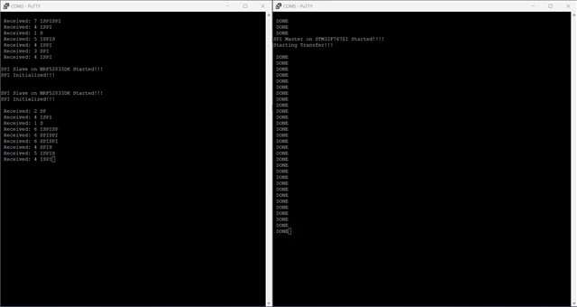
I need to set up communication between STM32FZI (Acting as Master) and NRF52833DK (Acting as Slave). But when I use the spis slave example in the NRF5 SDK, the communication is established but the data received is not the correct size. I am sending the message "SPI" from the STM32 but on the receiving end sometimes "SPIS", "PIS", and "P" is seen. I have checked using the oscilloscope and the data sent on the MOSI line is correct and the bytes represent "SPI". When and how does the spis_event_handler get called exactly? Since there is only one function (namely nrf_drv_spis_buffers_set) to execute the transfer while multiple are present in STM32F7 API, how does the DMA function?
#include "main.h"
enum {
TRANSFER_WAIT,
TRANSFER_COMPLETE,
TRANSFER_ERROR
};
UART_HandleTypeDef UartHandle;
#ifdef __GNUC__
/* With GCC, small printf (option LD Linker->Libraries->Small printf
set to 'Yes') calls __io_putchar() */
#define PUTCHAR_PROTOTYPE int __io_putchar(int ch)
#else
#define PUTCHAR_PROTOTYPE int fputc(int ch, FILE *f)
#endif /* __GNUC__ */
/* SPI handler declaration */
SPI_HandleTypeDef SpiHandle;
/* Buffer used for transmission */
uint8_t aTxBuffer[] = "SPI";
/* Buffer used for reception */
uint8_t aRxBuffer[BUFFERSIZE];
/* transfer state */
__IO uint32_t wTransferState = TRANSFER_WAIT;
/* Private function prototypes -----------------------------------------------*/
static void MPU_Config(void);
static void SystemClock_Config(void);
static void Error_Handler(void);
static void CPU_CACHE_Enable(void);
/* Private functions ---------------------------------------------------------*/
PUTCHAR_PROTOTYPE
{
HAL_UART_Transmit(&UartHandle, (uint8_t *)&ch, 1, 0xFFFF);
return ch;
}
int main(void)
{
MPU_Config();
CPU_CACHE_Enable();
HAL_Init();
SystemClock_Config();
BSP_LED_Init(LED1);
BSP_LED_Init(LED2);
BSP_LED_Init(LED3);
UartHandle.Instance = USARTx;
UartHandle.Init.BaudRate = 115200;
UartHandle.Init.WordLength = UART_WORDLENGTH_8B;
UartHandle.Init.StopBits = UART_STOPBITS_1;
UartHandle.Init.Parity = UART_PARITY_NONE;
UartHandle.Init.HwFlowCtl = UART_HWCONTROL_NONE;
UartHandle.Init.Mode = UART_MODE_TX_RX;
UartHandle.Init.OverSampling = UART_OVERSAMPLING_16;
if (HAL_UART_Init(&UartHandle) != HAL_OK)
{
Error_Handler();
}
printf("\r\nSPI Master on STM32F767ZI Started!!!! \r\n");
SpiHandle.Instance = SPIx;
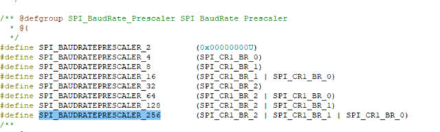
SpiHandle.Init.BaudRatePrescaler = SPI_BAUDRATEPRESCALER_256;
SpiHandle.Init.Direction = SPI_DIRECTION_2LINES;
SpiHandle.Init.CLKPhase = SPI_PHASE_1EDGE;
SpiHandle.Init.CLKPolarity = SPI_POLARITY_LOW;
SpiHandle.Init.DataSize = SPI_DATASIZE_8BIT;
SpiHandle.Init.FirstBit = SPI_FIRSTBIT_MSB;
SpiHandle.Init.TIMode = SPI_TIMODE_DISABLE;
SpiHandle.Init.CRCCalculation = SPI_CRCCALCULATION_DISABLE;
SpiHandle.Init.CRCPolynomial = 7;
SpiHandle.Init.NSS = SPI_NSS_HARD_OUTPUT;
SpiHandle.Init.Mode = SPI_MODE_MASTER;
if(HAL_SPI_Init(&SpiHandle) != HAL_OK)
{
Error_Handler();
}
printf("Starting Transfer!!! \r\n");
while (1)
{
if(HAL_SPI_TransmitReceive_IT(&SpiHandle, aTxBuffer, aRxBuffer, BUFFERSIZE) != HAL_OK)
{
Error_Handler();
}
while (wTransferState == TRANSFER_WAIT) {}
if (wTransferState == TRANSFER_COMPLETE) {
printf("\r\n DONE");
}
else {
printf("\r\n ERROR!!!");
}
HAL_Delay(2000);
}
}
/**
* @brief System Clock Configuration
* The system Clock is configured as follow :
* System Clock source = PLL (HSE)
* SYSCLK(Hz) = 216000000
* HCLK(Hz) = 216000000
* AHB Prescaler = 1
* APB1 Prescaler = 4
* APB2 Prescaler = 2
* HSE Frequency(Hz) = 8000000
* PLL_M = 8
* PLL_N = 432
* PLL_P = 2
* PLL_Q = 9
* PLL_R = 7
* VDD(V) = 3.3
* Main regulator output voltage = Scale1 mode
* Flash Latency(WS) = 7
* @param None
* @retval None
*/
void SystemClock_Config(void)
{
RCC_ClkInitTypeDef RCC_ClkInitStruct;
RCC_OscInitTypeDef RCC_OscInitStruct;
/* Enable HSE Oscillator and activate PLL with HSE as source */
RCC_OscInitStruct.OscillatorType = RCC_OSCILLATORTYPE_HSE;
RCC_OscInitStruct.HSEState = RCC_HSE_BYPASS;
RCC_OscInitStruct.HSIState = RCC_HSI_OFF;
RCC_OscInitStruct.PLL.PLLState = RCC_PLL_ON;
RCC_OscInitStruct.PLL.PLLSource = RCC_PLLSOURCE_HSE;
RCC_OscInitStruct.PLL.PLLM = 8;
RCC_OscInitStruct.PLL.PLLN = 432;
RCC_OscInitStruct.PLL.PLLP = RCC_PLLP_DIV2;
RCC_OscInitStruct.PLL.PLLQ = 9;
RCC_OscInitStruct.PLL.PLLR = 7;
if(HAL_RCC_OscConfig(&RCC_OscInitStruct) != HAL_OK)
{
while(1) {};
}
/* Activate the OverDrive to reach the 216 Mhz Frequency */
if(HAL_PWREx_EnableOverDrive() != HAL_OK)
{
while(1) {};
}
/* Select PLL as system clock source and configure the HCLK, PCLK1 and PCLK2
clocks dividers */
RCC_ClkInitStruct.ClockType = (RCC_CLOCKTYPE_SYSCLK | RCC_CLOCKTYPE_HCLK | RCC_CLOCKTYPE_PCLK1 | RCC_CLOCKTYPE_PCLK2);
RCC_ClkInitStruct.SYSCLKSource = RCC_SYSCLKSOURCE_PLLCLK;
RCC_ClkInitStruct.AHBCLKDivider = RCC_SYSCLK_DIV1;
RCC_ClkInitStruct.APB1CLKDivider = RCC_HCLK_DIV4;
RCC_ClkInitStruct.APB2CLKDivider = RCC_HCLK_DIV2;
if(HAL_RCC_ClockConfig(&RCC_ClkInitStruct, FLASH_LATENCY_7) != HAL_OK)
{
while(1) {};
}
}
/**
* @brief Tx Transfer completed callback.
* @param hspi: SPI handle
* @note This example shows a simple way to report end of Interrupt Tx transfer, and
* you can add your own implementation.
* @retval None
*/
void HAL_SPI_TxRxCpltCallback(SPI_HandleTypeDef *hspi)
{
/* Turn LED on: Transfer in transmission process is correct */
BSP_LED_On(LED1);
/* Turn LED on: Transfer in reception process is correct */
BSP_LED_On(LED2);
wTransferState = TRANSFER_COMPLETE;
}
/**
* @brief SPI error callbacks.
* @param hspi: SPI handle
* @note This example shows a simple way to report transfer error, and you can
* add your own implementation.
* @retval None
*/
void HAL_SPI_ErrorCallback(SPI_HandleTypeDef *hspi)
{
wTransferState = TRANSFER_ERROR;
}
/**
* @brief This function is executed in case of error occurrence.
* @param None
* @retval None
*/
static void Error_Handler(void)
{
/* Turn LED3 on */
BSP_LED_On(LED3);
while (1)
{
}
}
/**
* @brief CPU L1-Cache enable.
* @param None
* @retval None
*/
static void CPU_CACHE_Enable(void)
{
/* Enable I-Cache */
SCB_EnableICache();
/* Enable D-Cache */
SCB_EnableDCache();
}
/**
* @brief Configure the MPU attributes
* @param None
* @retval None
*/
static void MPU_Config(void)
{
MPU_Region_InitTypeDef MPU_InitStruct;
/* Disable the MPU */
HAL_MPU_Disable();
/* Configure the MPU as Strongly ordered for not defined regions */
MPU_InitStruct.Enable = MPU_REGION_ENABLE;
MPU_InitStruct.BaseAddress = 0x00;
MPU_InitStruct.Size = MPU_REGION_SIZE_4GB;
MPU_InitStruct.AccessPermission = MPU_REGION_NO_ACCESS;
MPU_InitStruct.IsBufferable = MPU_ACCESS_NOT_BUFFERABLE;
MPU_InitStruct.IsCacheable = MPU_ACCESS_NOT_CACHEABLE;
MPU_InitStruct.IsShareable = MPU_ACCESS_SHAREABLE;
MPU_InitStruct.Number = MPU_REGION_NUMBER0;
MPU_InitStruct.TypeExtField = MPU_TEX_LEVEL0;
MPU_InitStruct.SubRegionDisable = 0x87;
MPU_InitStruct.DisableExec = MPU_INSTRUCTION_ACCESS_DISABLE;
HAL_MPU_ConfigRegion(&MPU_InitStruct);
/* Enable the MPU */
HAL_MPU_Enable(MPU_PRIVILEGED_DEFAULT);
}
#ifdef USE_FULL_ASSERT
/**
* @brief Reports the name of the source file and the source line number
* where the assert_param error has occurred.
* @param file: pointer to the source file name
* @param line: assert_param error line source number
* @retval None
*/
void assert_failed(uint8_t *file, uint32_t line)
{
/* User can add his own implementation to report the file name and line number,
ex: printf("Wrong parameters value: file %s on line %d\r\n", file, line) */
/* Infinite loop */
while (1)
{
}
}
#endif
/**
* @}
*/
/**
* @}
*/
#include "sdk_config.h"
#include "nrf_drv_spis.h"
#include "nrf_gpio.h"
#include "boards.h"
#include "app_error.h"
#include <string.h>
#include "nrf_delay.h"

#include "nrf_uart.h"
#include "app_uart.h"

#include <stdio.h>

#define SPIS_INSTANCE 1
static const nrf_drv_spis_t spis = NRF_DRV_SPIS_INSTANCE(SPIS_INSTANCE);

#define BUFSIZE 7
static uint8_t       m_tx_buf[BUFSIZE] = "NORDIC";
static uint8_t       m_rx_buf[BUFSIZE];

static volatile bool spis_xfer_done;
static volatile size_t spis_amount;


void spis_event_handler(nrf_drv_spis_event_t event)
{
    if (event.evt_type == NRF_DRV_SPIS_XFER_DONE)
    {
        spis_xfer_done = true;
				spis_amount = event.rx_amount ;
    }
}

#define UART_TX_BUF_SIZE 256                         /**< UART TX buffer size. */
#define UART_RX_BUF_SIZE 256                         /**< UART RX buffer size. */

void uart_error_handle(app_uart_evt_t * p_event)
{
    if (p_event->evt_type == APP_UART_COMMUNICATION_ERROR)
    {
        APP_ERROR_HANDLER(p_event->data.error_communication);
    }
    else if (p_event->evt_type == APP_UART_FIFO_ERROR)
    {
        APP_ERROR_HANDLER(p_event->data.error_code);
    }
}

int main(void)
{
    NRF_POWER->TASKS_CONSTLAT = 1;

    bsp_board_init(BSP_INIT_LEDS);

		uint32_t err_code;

		const app_uart_comm_params_t comm_params =
      {
          RX_PIN_NUMBER,
          TX_PIN_NUMBER,
          RTS_PIN_NUMBER,
          CTS_PIN_NUMBER,
          APP_UART_FLOW_CONTROL_DISABLED,
          false,
          NRF_UART_BAUDRATE_115200
      };

    APP_UART_FIFO_INIT(&comm_params,
                         UART_RX_BUF_SIZE,
                         UART_TX_BUF_SIZE,
                         uart_error_handle,
                         APP_IRQ_PRIORITY_LOW,
                         err_code);

    APP_ERROR_CHECK(err_code);

		printf("\r\n\r\nSPI Slave on NRF52833DK Started!!! \r\n");

    nrf_drv_spis_config_t spis_config = NRF_DRV_SPIS_DEFAULT_CONFIG;
		spis_config.sck_pin               = 28;
    spis_config.miso_pin              = 29;
    spis_config.mosi_pin              = 30;
		spis_config.csn_pin               = 31;

    APP_ERROR_CHECK(nrf_drv_spis_init(&spis, &spis_config, spis_event_handler));

		printf("SPI Initialized!!! \r\n");

    while (1)
    {
        memset(m_rx_buf, 0, BUFSIZE);
        spis_xfer_done = false;

			APP_ERROR_CHECK(nrf_drv_spis_buffers_set(&spis, m_tx_buf , BUFSIZE ,m_rx_buf, BUFSIZE));

			while (!spis_xfer_done)
        {
            __WFE();
        }

				printf("\r\n Received: %d %s", spis_amount ,(const char *)m_rx_buf);

        bsp_board_led_invert(BSP_BOARD_LED_0);
    }
}
COM3 - NRF52833 , COM5 - STM32f7