Overview
Hi
I have the nRF9160DK and I have had a really good experience with it so far getting MCU, Modem, LTE, GNSS, Logging and CoAP working.
The challenge is now that I have to connect another sensor development board, which needs to communicate with nRF9160 as an SPI slave. To verify that I can get SPI to work as intended, and transmit reliably I have decided to make a small loopback test.
The plan is to activate SPI3 as master and SPI2 as slave, then configure SPI3 MISO <---> SPI2 MOSI and vice versa, and last SPI3 SCK <---> SPI2 SCK to the same pin. I leave Chip-select out as there's only one slave. Not sure if this is alright?
My problems are:
- Is the described idea even possible?
- If not then how would you suggest achieving this SPI verification?
- In my current test logging through default, UART via USB doesn't work.
- Commenting out two lines with 'spi_read_dt()' and 'spi_write_dt()' makes logging work again for some reason.
- Is my prj.conf correct for this SPI configuration?
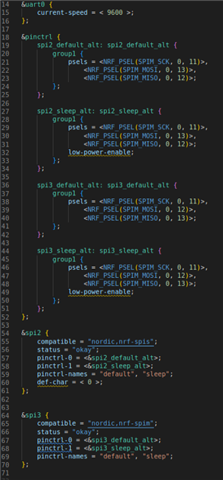
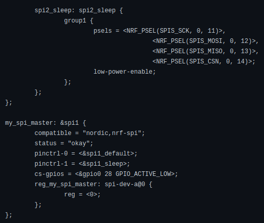
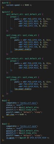
- Is my devicetree overlay file correct for this SPI configuration?
- In general, my understanding of devicetrees struggles, especially the use of 'pinctrl' over the deprecated miso-pin, mosi-pin etc.
Code explanation
The program starts by getting the device pointers to spi2 and spi3, and then specifying a global spi spec pointer, so that it can be used in the thread reading the spi2. It defines a semaphore to make sure that the echo thread doesn't read before the spi2 spec is set up properly.
The function 'echo()' is the entry point of the thread which just, after taking the semaphore, reads from the spi2 into a local buffer and prints the received buffer to the terminal.
'Main()' makes sure to set up spi2 and spi3 with the same configuration except for master and slave modes. Then it initializes the LEDs, so LED1 and LED2 can visualize where we are in the code. Then we're checking that spi2 and spi3 is ready(spi2 already a pointer and spi3 isn't). We're now turning the first LED on, set up the tx buffer and then wait for a second, so that the LED can properly light up before we try to write to spi3. If an error occurs we light up LED4, and give it around 5 secs so it's clearly visible.
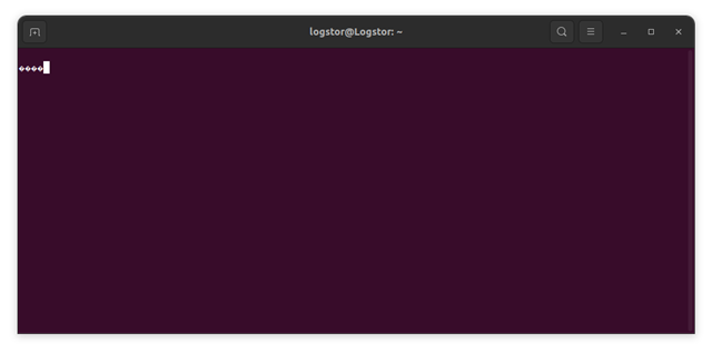
What happens
It starts up, but doesn't print anything to the serial terminal. Then the first LED lights up for about 1 second, and this cycle will continue forever.
Files
2860.prj.conf
/*
 * Copyright (c) 2012-2014 Wind River Systems, Inc.
 *
 * SPDX-License-Identifier: Apache-2.0
 */

#include <zephyr/kernel.h>
#include <zephyr/logging/log.h>
#include <zephyr/devicetree.h>
#include <zephyr/device.h>
#include <zephyr/drivers/spi.h>

#include <dk_buttons_and_leds.h>

#define MAIN_LOOP_SLEEP 30000
#define SPI_TEST_MESSAGE "Hello from SPI"

// Logging
LOG_MODULE_REGISTER(SPITest, LOG_LEVEL_DBG);

// Retrieve SPI Nodes
static const struct device* dev_spi2 = DEVICE_DT_GET(DT_NODELABEL(spi2));
static const struct device* dev_spi3 = DEVICE_DT_GET(DT_NODELABEL(spi3));
static struct spi_dt_spec* spi2;

// Define semaphores
K_SEM_DEFINE(sem_spi, 0, 1);

// Prototypes
void echo();

// Define SPI echo thread
K_THREAD_DEFINE(spi_echo, 1024, echo, NULL, NULL, NULL, 7, 0, 10);

void echo()
{
	printk("Echo thread started\n");
	k_sem_take(&sem_spi, K_FOREVER);
	printk("Echo thread taken semaphore\n");

	uint8_t buf[128];
	struct spi_buf rx_buf = {
		.buf = buf,
		.len = sizeof(buf)
	};
	struct spi_buf_set rx_buf_set = {
		.buffers = &rx_buf,
		.count = 1
	};

	spi_read_dt((const struct spi_dt_spec*)spi2, &rx_buf_set);

	printk("Received: %s\n", buf);
}

void main(void)
{
	printk("Hello World! %s\n", CONFIG_BOARD);

	struct spi_dt_spec _spi2 = {
		.bus = dev_spi2,
		.config = {
			.frequency = 5000,
			.operation = SPI_OP_MODE_SLAVE | SPI_WORD_SET(8) | SPI_TRANSFER_MSB,
			.slave = 0,
			.cs = NULL
		}
	};
	spi2 = &_spi2;

	const struct spi_dt_spec spi3 = {
		.bus = dev_spi3,
		.config = {
			.frequency = 5000,
			.operation = SPI_OP_MODE_MASTER | SPI_WORD_SET(8) | SPI_TRANSFER_MSB,
			.slave = 0,
			.cs = NULL
		}
	};

	// Init LEDs
	int err = dk_leds_init();
	if (err)
	{
		printk("LEDs couldn't be initialized");
		return;
	}

	// Check if SPI is ready
	if (!spi_is_ready_dt(&spi3) && !spi_is_ready_dt(spi2))
	{
		LOG_ERR("SPI wasn't ready!");
		return;
	}

	k_sem_give(&sem_spi);

	printk("SPI is ready\n");
	dk_set_led_on(DK_LED1);

	printk("Trying to write something\n");

	const struct spi_buf tx_buf = {
		.buf = SPI_TEST_MESSAGE,
		.len = sizeof(SPI_TEST_MESSAGE)
	};
	const struct spi_buf_set tx_buf_set = {
		.buffers = &tx_buf,
		.count = 1
	};

	k_msleep(1000); // Make sure LED1 is visible before crash
	err = spi_write_dt(&spi3, &tx_buf_set);
	if (err)
	{
		printk("An error happened during transceive, code %d", errno);
		dk_set_led_on(DK_LED4);
		return;
	}
	dk_set_led_on(DK_LED2);

	printk("Done writing to SPI\n");

	while(1)
	{
		k_msleep(MAIN_LOOP_SLEEP);
	}
}