I'm using Seeed XIAO nrf52840 and tried matter cluster as below.
I'm using master branch on Matter SDK.
https://github.com/project-chip/connectedhomeip/tree/master/examples/lighting-app/nrfconnect
I modified `boards/nrf52840dk_nrf52840.overlay` file as below.
/ {
	chosen {
		nordic,pm-ext-flash = &p25q16h_spi;
	};

	/*
	* In some default configurations within the nRF Connect SDK,
	* e.g. on nRF52840, the chosen zephyr,entropy node is &cryptocell.
	* This devicetree overlay ensures that default is overridden wherever it
	* is set, as this application uses the RNG node for entropy exclusively.
	*/
/delete-property/ arduino_header;
/delete-property/ connector;
/delete-property/ arduino_adc;
/delete-property/ analog-connector;


/delete-property/ spi1;
/delete-property/ spi2;
/delete-property/ uart1;
/delete-property/ i2c0;
/delete-property/ arduino_serial;
/delete-property/ arduino_i2c;

/delete-node/ spi1;
/delete-node/ spi2;
/delete-node/ uart1;
/delete-node/ i2c0;
/delete-node/ arduino_serial;
/delete-node/ arduino_i2c;


	chosen {
		zephyr,entropy = &rng;
	};

    leds {
            compatible = "gpio-leds";
            led0: led_0 {
                    gpios = <&gpio0 17 GPIO_ACTIVE_LOW>;
                    label = "Green LED 0";
            };
            led1: led_1 {
                    gpios = <&gpio0 26 GPIO_ACTIVE_LOW>;
                    label = "Red LED 1";
            };
            led2: led_2 {
                    gpios = <&gpio0 30 GPIO_ACTIVE_LOW>;
                    label = "Green LED 2";
            };
            led3: led_3 {
                    gpios = <&gpio0 6 GPIO_ACTIVE_LOW>;
                    label = "Blue LED 3";
            };
    };
    buttons {
            compatible = "gpio-keys";
            button0: button_0 {
                    gpios = <&gpio1 15 (GPIO_PULL_UP | GPIO_ACTIVE_LOW)>;
                    label = "Push button switch 0";
            };
            button1: button_1 {
                    gpios = <&gpio1 14 (GPIO_PULL_UP | GPIO_ACTIVE_LOW)>;
                    label = "Push button switch 1";
            };
            button2: button_2 {
                    gpios = <&gpio0 2 (GPIO_PULL_UP | GPIO_ACTIVE_LOW)>;
                    label = "Push button switch 2";
            };
            button3: button_3 {
                    gpios = <&gpio0 3 (GPIO_PULL_UP | GPIO_ACTIVE_LOW)>;
                    label = "Push button switch 3";
            };
    };


	/*
	* By default, PWM module is only configured for led0 (LED1 on the board).
	* The lighting-app, however, uses LED2 to show the state of the lighting,
	* including its brightness level.
	*/
	aliases {
		pwm-led1 = &pwm_led1;
	};

	pwmleds {
		pwm_led1: pwm_led_1 {
			pwms = <&pwm0 1 PWM_MSEC(20) PWM_POLARITY_INVERTED>;
		};
	};

};

&pwm0 {
	pinctrl-0 = <&pwm0_default_alt>;
	pinctrl-1 = <&pwm0_sleep_alt>;
	pinctrl-names = "default", "sleep";
};

&uart0{
	/delete-property/ rts-pin;
	/delete-property/ cts-pin;
	/delete-property/ hw-flow-control;
};


&pinctrl {

	pwm0_default_alt: pwm0_default_alt {
		group1 {
			psels = <NRF_PSEL(PWM_OUT1, 0, 26)>;
			nordic,invert;
		};
	};

	pwm0_sleep_alt: pwm0_sleep_alt {
		group1 {
			psels = <NRF_PSEL(PWM_OUT1, 0, 26)>;
			low-power-enable;
		};
	};

	uart0_default: uart0_default {
		group1 {
			psels = <NRF_PSEL(UART_TX, 1, 11)>,
				<NRF_PSEL(UART_RX, 1, 12)>;
		};
	};

	uart0_sleep: uart0_sleep {
		group1 {
			psels = <NRF_PSEL(UART_TX, 1, 11)>,
				<NRF_PSEL(UART_RX, 1, 12)>;
			low-power-enable;
		};
	};

    spi3_default: spi3_default {
            group1 {
                    psels = <NRF_PSEL(SPIM_SCK, 0, 21)>,
                            <NRF_PSEL(SPIM_MOSI, 0, 20)>,
                            <NRF_PSEL(SPIM_MISO, 0, 24)>;
            };
    };

    spi3_sleep: spi3_sleep {
            group1 {
                    psels = <NRF_PSEL(SPIM_SCK, 0, 21)>,
                            <NRF_PSEL(SPIM_MOSI, 0, 20)>,
                            <NRF_PSEL(SPIM_MISO, 0, 24)>;
                    low-power-enable;
            };
    };

    qspi_default: qspi_default {
            group1 {
                    psels = <NRF_PSEL(QSPI_SCK, 0, 21)>,
                            <NRF_PSEL(QSPI_IO0, 0, 20)>,
                            <NRF_PSEL(QSPI_IO1, 0, 24)>,
                            <NRF_PSEL(QSPI_IO2, 0, 22)>,
                            <NRF_PSEL(QSPI_IO3, 0, 23)>,
                            <NRF_PSEL(QSPI_CSN, 0, 25)>;
            };
    };

    qspi_sleep: qspi_sleep {
            group1 {
                    psels = <NRF_PSEL(QSPI_SCK, 0, 21)>,
                            <NRF_PSEL(QSPI_IO0, 0, 20)>,
                            <NRF_PSEL(QSPI_IO1, 0, 24)>,
                            <NRF_PSEL(QSPI_IO2, 0, 22)>,
                            <NRF_PSEL(QSPI_IO3, 0, 23)>,
                            <NRF_PSEL(QSPI_CSN, 0, 25)>;
                    low-power-enable;
            };
    };

};


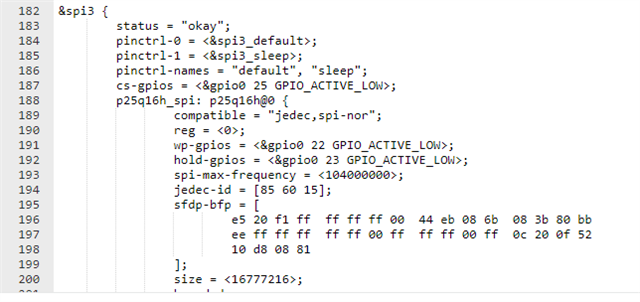
&spi3 {
        status = "okay";
        pinctrl-0 = <&spi3_default>;
        pinctrl-1 = <&spi3_sleep>;
        pinctrl-names = "default", "sleep";
        cs-gpios = <&gpio0 25 GPIO_ACTIVE_LOW>;
        p25q16h_spi: p25q16h@0 {
                compatible = "jedec,spi-nor";
                reg = <0>;
                wp-gpios = <&gpio0 22 GPIO_ACTIVE_LOW>;
                hold-gpios = <&gpio0 23 GPIO_ACTIVE_LOW>;
                spi-max-frequency = <104000000>;
                jedec-id = [85 60 15];
                sfdp-bfp = [
                        e5 20 f1 ff  ff ff ff 00  44 eb 08 6b  08 3b 80 bb
                        ee ff ff ff  ff ff 00 ff  ff ff 00 ff  0c 20 0f 52
                        10 d8 08 81
                ];
                size = <16777216>;
                has-dpd;
                t-enter-dpd = <3000>;
                t-exit-dpd = <8000>;
        };
};
and I modified `configuration/nrf52840dk_nrf52840/pm_static_dfu.yml` as below.
mcuboot:
    address: 0x0
    size: 0x7000
    region: flash_primary
mcuboot_pad:
    address: 0x7000
    size: 0x200
app:
    address: 0x7200
    size: 0xf3e00
mcuboot_primary:
    orig_span: &id001
        - mcuboot_pad
        - app
    span: *id001
    address: 0x7000
    size: 0xf4000
    region: flash_primary
mcuboot_primary_app:
    orig_span: &id002
        - app
    span: *id002
    address: 0x7200
    size: 0xf3e00
factory_data:
    address: 0xfb000
    size: 0x1000
    region: flash_primary
settings_storage:
    address: 0xfc000
    size: 0x4000
    region: flash_primary
mcuboot_secondary:
    address: 0x0
    size: 0xf4000
    device: p25q16h_spi
    region: external_flash
external_flash:
    address: 0xf4000
    size: 0x10C000
    device: p25q16h_spi
    region: external_flash
I built with command `west build -b nrf52840dk_nrf52840`.
Then, below error occurred.
/home/muto/gcc-arm/gcc-arm-none-eabi-10.3-2021.10/bin/../lib/gcc/arm-none-eabi/10.3.1/../../../../arm-none-eabi/bin/ld.bfd: modules/nrf/subsys/dfu/dfu_target/lib..__nrf__subsys__dfu__dfu_target.a(dfu_target_mcuboot.c.obj): in function `dfu_target_mcuboot_init':
/home/muto/ncs/nrf/subsys/dfu/dfu_target/src/dfu_target_mcuboot.c:153: undefined reference to `__device_dts_ord_137'
/home/muto/gcc-arm/gcc-arm-none-eabi-10.3-2021.10/bin/../lib/gcc/arm-none-eabi/10.3.1/../../../../arm-none-eabi/bin/ld.bfd: zephyr/libzephyr.a(flash_map_partition_manager.c.obj):(.rodata.default_flash_map+0x1c): undefined reference to `__device_dts_ord_137'
/home/muto/gcc-arm/gcc-arm-none-eabi-10.3-2021.10/bin/../lib/gcc/arm-none-eabi/10.3.1/../../../../arm-none-eabi/bin/ld.bfd: zephyr/libzephyr.a(flash_map_partition_manager.c.obj):(.rodata.default_flash_map+0x6c): undefined reference to `__device_dts_ord_137'
collect2: error: ld returned 1 exit status
ninja: build stopped: subcommand failed.
how do I resolve it?


