matter with Seed XIAO nrf52840

I'm using Seeed XIAO nrf52840 and tried matter cluster as below.

I'm using master branch on Matter SDK.

https://github.com/project-chip/connectedhomeip/tree/master/examples/lighting-app/nrfconnect

I modified `boards/nrf52840dk_nrf52840.overlay` file as below.

/ {
	chosen {
		nordic,pm-ext-flash = &p25q16h_spi;
	};

	/*
	* In some default configurations within the nRF Connect SDK,
	* e.g. on nRF52840, the chosen zephyr,entropy node is &cryptocell.
	* This devicetree overlay ensures that default is overridden wherever it
	* is set, as this application uses the RNG node for entropy exclusively.
	*/
/delete-property/ arduino_header;
/delete-property/ connector;
/delete-property/ arduino_adc;
/delete-property/ analog-connector;


/delete-property/ spi1;
/delete-property/ spi2;
/delete-property/ uart1;
/delete-property/ i2c0;
/delete-property/ arduino_serial;
/delete-property/ arduino_i2c;

/delete-node/ spi1;
/delete-node/ spi2;
/delete-node/ uart1;
/delete-node/ i2c0;
/delete-node/ arduino_serial;
/delete-node/ arduino_i2c;


	chosen {
		zephyr,entropy = &rng;
	};

    leds {
            compatible = "gpio-leds";
            led0: led_0 {
                    gpios = <&gpio0 17 GPIO_ACTIVE_LOW>;
                    label = "Green LED 0";
            };
            led1: led_1 {
                    gpios = <&gpio0 26 GPIO_ACTIVE_LOW>;
                    label = "Red LED 1";
            };
            led2: led_2 {
                    gpios = <&gpio0 30 GPIO_ACTIVE_LOW>;
                    label = "Green LED 2";
            };
            led3: led_3 {
                    gpios = <&gpio0 6 GPIO_ACTIVE_LOW>;
                    label = "Blue LED 3";
            };
    };
    buttons {
            compatible = "gpio-keys";
            button0: button_0 {
                    gpios = <&gpio1 15 (GPIO_PULL_UP | GPIO_ACTIVE_LOW)>;
                    label = "Push button switch 0";
            };
            button1: button_1 {
                    gpios = <&gpio1 14 (GPIO_PULL_UP | GPIO_ACTIVE_LOW)>;
                    label = "Push button switch 1";
            };
            button2: button_2 {
                    gpios = <&gpio0 2 (GPIO_PULL_UP | GPIO_ACTIVE_LOW)>;
                    label = "Push button switch 2";
            };
            button3: button_3 {
                    gpios = <&gpio0 3 (GPIO_PULL_UP | GPIO_ACTIVE_LOW)>;
                    label = "Push button switch 3";
            };
    };


	/*
	* By default, PWM module is only configured for led0 (LED1 on the board).
	* The lighting-app, however, uses LED2 to show the state of the lighting,
	* including its brightness level.
	*/
	aliases {
		pwm-led1 = &pwm_led1;
	};

	pwmleds {
		pwm_led1: pwm_led_1 {
			pwms = <&pwm0 1 PWM_MSEC(20) PWM_POLARITY_INVERTED>;
		};
	};

};

&pwm0 {
	pinctrl-0 = <&pwm0_default_alt>;
	pinctrl-1 = <&pwm0_sleep_alt>;
	pinctrl-names = "default", "sleep";
};

&uart0{
	/delete-property/ rts-pin;
	/delete-property/ cts-pin;
	/delete-property/ hw-flow-control;
};


&pinctrl {

	pwm0_default_alt: pwm0_default_alt {
		group1 {
			psels = <NRF_PSEL(PWM_OUT1, 0, 26)>;
			nordic,invert;
		};
	};

	pwm0_sleep_alt: pwm0_sleep_alt {
		group1 {
			psels = <NRF_PSEL(PWM_OUT1, 0, 26)>;
			low-power-enable;
		};
	};

	uart0_default: uart0_default {
		group1 {
			psels = <NRF_PSEL(UART_TX, 1, 11)>,
				<NRF_PSEL(UART_RX, 1, 12)>;
		};
	};

	uart0_sleep: uart0_sleep {
		group1 {
			psels = <NRF_PSEL(UART_TX, 1, 11)>,
				<NRF_PSEL(UART_RX, 1, 12)>;
			low-power-enable;
		};
	};

    spi3_default: spi3_default {
            group1 {
                    psels = <NRF_PSEL(SPIM_SCK, 0, 21)>,
                            <NRF_PSEL(SPIM_MOSI, 0, 20)>,
                            <NRF_PSEL(SPIM_MISO, 0, 24)>;
            };
    };

    spi3_sleep: spi3_sleep {
            group1 {
                    psels = <NRF_PSEL(SPIM_SCK, 0, 21)>,
                            <NRF_PSEL(SPIM_MOSI, 0, 20)>,
                            <NRF_PSEL(SPIM_MISO, 0, 24)>;
                    low-power-enable;
            };
    };

    qspi_default: qspi_default {
            group1 {
                    psels = <NRF_PSEL(QSPI_SCK, 0, 21)>,
                            <NRF_PSEL(QSPI_IO0, 0, 20)>,
                            <NRF_PSEL(QSPI_IO1, 0, 24)>,
                            <NRF_PSEL(QSPI_IO2, 0, 22)>,
                            <NRF_PSEL(QSPI_IO3, 0, 23)>,
                            <NRF_PSEL(QSPI_CSN, 0, 25)>;
            };
    };

    qspi_sleep: qspi_sleep {
            group1 {
                    psels = <NRF_PSEL(QSPI_SCK, 0, 21)>,
                            <NRF_PSEL(QSPI_IO0, 0, 20)>,
                            <NRF_PSEL(QSPI_IO1, 0, 24)>,
                            <NRF_PSEL(QSPI_IO2, 0, 22)>,
                            <NRF_PSEL(QSPI_IO3, 0, 23)>,
                            <NRF_PSEL(QSPI_CSN, 0, 25)>;
                    low-power-enable;
            };
    };

};


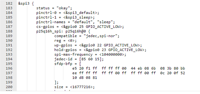
&spi3 {
        status = "okay";
        pinctrl-0 = <&spi3_default>;
        pinctrl-1 = <&spi3_sleep>;
        pinctrl-names = "default", "sleep";
        cs-gpios = <&gpio0 25 GPIO_ACTIVE_LOW>;
        p25q16h_spi: p25q16h@0 {
                compatible = "jedec,spi-nor";
                reg = <0>;
                wp-gpios = <&gpio0 22 GPIO_ACTIVE_LOW>;
                hold-gpios = <&gpio0 23 GPIO_ACTIVE_LOW>;
                spi-max-frequency = <104000000>;
                jedec-id = [85 60 15];
                sfdp-bfp = [
                        e5 20 f1 ff  ff ff ff 00  44 eb 08 6b  08 3b 80 bb
                        ee ff ff ff  ff ff 00 ff  ff ff 00 ff  0c 20 0f 52
                        10 d8 08 81
                ];
                size = <16777216>;
                has-dpd;
                t-enter-dpd = <3000>;
                t-exit-dpd = <8000>;
        };
};

and I modified `configuration/nrf52840dk_nrf52840/pm_static_dfu.yml` as below.

mcuboot:
    address: 0x0
    size: 0x7000
    region: flash_primary
mcuboot_pad:
    address: 0x7000
    size: 0x200
app:
    address: 0x7200
    size: 0xf3e00
mcuboot_primary:
    orig_span: &id001
        - mcuboot_pad
        - app
    span: *id001
    address: 0x7000
    size: 0xf4000
    region: flash_primary
mcuboot_primary_app:
    orig_span: &id002
        - app
    span: *id002
    address: 0x7200
    size: 0xf3e00
factory_data:
    address: 0xfb000
    size: 0x1000
    region: flash_primary
settings_storage:
    address: 0xfc000
    size: 0x4000
    region: flash_primary
mcuboot_secondary:
    address: 0x0
    size: 0xf4000
    device: p25q16h_spi
    region: external_flash
external_flash:
    address: 0xf4000
    size: 0x10C000
    device: p25q16h_spi
    region: external_flash

I built with command `west build -b nrf52840dk_nrf52840`.

Then, below error occurred.

/home/muto/gcc-arm/gcc-arm-none-eabi-10.3-2021.10/bin/../lib/gcc/arm-none-eabi/10.3.1/../../../../arm-none-eabi/bin/ld.bfd: modules/nrf/subsys/dfu/dfu_target/lib..__nrf__subsys__dfu__dfu_target.a(dfu_target_mcuboot.c.obj): in function `dfu_target_mcuboot_init':
/home/muto/ncs/nrf/subsys/dfu/dfu_target/src/dfu_target_mcuboot.c:153: undefined reference to `__device_dts_ord_137'
/home/muto/gcc-arm/gcc-arm-none-eabi-10.3-2021.10/bin/../lib/gcc/arm-none-eabi/10.3.1/../../../../arm-none-eabi/bin/ld.bfd: zephyr/libzephyr.a(flash_map_partition_manager.c.obj):(.rodata.default_flash_map+0x1c): undefined reference to `__device_dts_ord_137'
/home/muto/gcc-arm/gcc-arm-none-eabi-10.3-2021.10/bin/../lib/gcc/arm-none-eabi/10.3.1/../../../../arm-none-eabi/bin/ld.bfd: zephyr/libzephyr.a(flash_map_partition_manager.c.obj):(.rodata.default_flash_map+0x6c): undefined reference to `__device_dts_ord_137'
collect2: error: ld returned 1 exit status
ninja: build stopped: subcommand failed.

how do I resolve it?

  • Hi, 

    What NCS version are you using?

    Do you also update the overlay file under child_image/mcuboot/boards?

    Regards,
    Amanda H.

  • Hi,

    I followed below install guide and installed NCS.

    https://developer.nordicsemi.com/nRF_Connect_SDK/doc/latest/nrf/getting_started/installing.html

    And, it was update automatically by "update_ncs.py" as below.

    https://github.com/project-chip/connectedhomeip/tree/master/examples/lighting-app/nrfconnect#using-native-shell-for-setup

    NCS version is 2.3.0.

    $ cat ~/ncs/nrf/VERSION
    2.3.0

    https://github.com/project-chip/connectedhomeip/tree/master/examples/lighting-app/nrfconnect

    ovarlay file is under "boards" in above example.

    it is not "child_image/mcuboot/boards".

    original "boards/nrf52840dk_nrf52840.overlay" does not fit Seeed XIAO nrf52840.

    So, I modify "boards/nrf52840dk_nrf52840.overlay".

    I tried to modify "child_image/mcuboot/boards/nrf52840dk_nrf52840.overlay" as below and build it.

    / {
    	chosen {
                    nordic,pm-ext-flash = &p25q16h_spi;
    	};
    };
    

    Then, below error message shows.

    -- Found devicetree overlay: /home/muto/ncs/bootloader/mcuboot/boot/zephyr/dts.overlay
    devicetree error: /chosen: undefined node label 'p25q16h_spi'

  • Hi, 

    child_image/mcuboot/boards/nrf52840dk_nrf52840.overlay should also have spi3 this part.

    -Amanda H.

  • Thank you for your reply.

    I add spi3 but it has failure.

    / {
    	chosen {
            nordic,pm-ext-flash = &p25q16h_spi;
    	};
    };
    
    &spi3 {
            status = "okay";
            pinctrl-0 = <&spi3_default>;
            pinctrl-1 = <&spi3_sleep>;
            pinctrl-names = "default", "sleep";
            cs-gpios = <&gpio0 25 GPIO_ACTIVE_LOW>;
            p25q16h_spi: p25q16h@0 {
                    compatible = "jedec,spi-nor";
                    reg = <0>;
                    wp-gpios = <&gpio0 22 GPIO_ACTIVE_LOW>;
                    hold-gpios = <&gpio0 23 GPIO_ACTIVE_LOW>;
                    spi-max-frequency = <104000000>;
                    jedec-id = [85 60 15];
                    sfdp-bfp = [
                            e5 20 f1 ff  ff ff ff 00  44 eb 08 6b  08 3b 80 bb
                            ee ff ff ff  ff ff 00 ff  ff ff 00 ff  0c 20 0f 52
                            10 d8 08 81
                    ];
                    size = <16777216>;
                    has-dpd;
                    t-enter-dpd = <3000>;
                    t-exit-dpd = <8000>;
            };
    };
    

    [2/179] Generating include/generated/version.h
    -- Zephyr version: 3.2.99 (/home/muto/ncs/zephyr), build: v3.2.99-ncs2
    [169/179] Linking C executable zephyr/zephyr_pre0.elf
    FAILED: zephyr/zephyr_pre0.elf zephyr/zephyr_pre0.map /home/muto/matter/matter-master-20230315/examples/lighting-app/nrfconnect/build/mcuboot/zephyr/zephyr_pre0.map 
    : && ccache /home/muto/gcc-arm/gcc-arm-none-eabi-10.3-2021.10/bin/arm-none-eabi-gcc  -gdwarf-4 zephyr/CMakeFiles/zephyr_pre0.dir/misc/empty_file.c.obj -o zephyr/zephyr_pre0.elf  zephyr/CMakeFiles/offsets.dir/./arch/arm/core/offsets/offsets.c.obj  -fuse-ld=bfd  -Wl,-T  zephyr/linker_zephyr_pre0.cmd  -Wl,-Map=/home/muto/matter/matter-master-20230315/examples/lighting-app/nrfconnect/build/mcuboot/zephyr/zephyr_pre0.map  -Wl,--whole-archive  app/libapp.a  zephyr/libzephyr.a  zephyr/arch/common/libarch__common.a  zephyr/arch/arch/arm/core/aarch32/libarch__arm__core__aarch32.a  zephyr/arch/arch/arm/core/aarch32/cortex_m/libarch__arm__core__aarch32__cortex_m.a  zephyr/arch/arch/arm/core/aarch32/mpu/libarch__arm__core__aarch32__mpu.a  zephyr/lib/libc/minimal/liblib__libc__minimal.a  zephyr/soc/arm/common/cortex_m/libsoc__arm__common__cortex_m.a  zephyr/soc/arm/nordic_nrf/nrf52/libsoc__arm__nordic_nrf__nrf52.a  zephyr/drivers/clock_control/libdrivers__clock_control.a  zephyr/drivers/flash/libdrivers__flash.a  zephyr/drivers/timer/libdrivers__timer.a  zephyr/drivers/pinctrl/libdrivers__pinctrl.a  modules/nrf/lib/fprotect/lib..__nrf__lib__fprotect.a  modules/nrf/drivers/hw_cc310/lib..__nrf__drivers__hw_cc310.a  modules/mcuboot/boot/bootutil/zephyr/libmcuboot_util.a  modules/hal_nordic/nrfx/libmodules__hal_nordic__nrfx.a  -Wl,--no-whole-archive  zephyr/kernel/libkernel.a  -L"/home/muto/gcc-arm/gcc-arm-none-eabi-10.3-2021.10/bin/../lib/gcc/arm-none-eabi/10.3.1/thumb/v7e-m+fp/hard"  -L/home/muto/matter/matter-master-20230315/examples/lighting-app/nrfconnect/build/mcuboot/zephyr  -lgcc  zephyr/arch/common/libisr_tables.a  -no-pie  -mcpu=cortex-m4  -mthumb  -mabi=aapcs  -mfpu=fpv4-sp-d16  -mfloat-abi=hard  -mfp16-format=ieee  -Wl,--gc-sections  -Wl,--build-id=none  -Wl,--sort-common=descending  -Wl,--sort-section=alignment  -Wl,-u,_OffsetAbsSyms  -Wl,-u,_ConfigAbsSyms  -nostdlib  -static  -Wl,-X  -Wl,-N  -Wl,--orphan-handling=warn  /home/muto/ncs/nrfxlib/crypto/nrf_cc310_platform/lib/cortex-m4/hard-float/no-interrupts/libnrf_cc310_platform_0.9.16.a  /home/muto/ncs/nrfxlib/crypto/nrf_cc310_bl/lib/cortex-m4/hard-float/no-interrupts/libnrf_cc310_bl_0.9.12.a && cd /home/muto/matter/matter-master-20230315/examples/lighting-app/nrfconnect/build/mcuboot/zephyr && /usr/bin/cmake -E echo
    /home/muto/gcc-arm/gcc-arm-none-eabi-10.3-2021.10/bin/../lib/gcc/arm-none-eabi/10.3.1/../../../../arm-none-eabi/bin/ld.bfd: zephyr/libzephyr.a(flash_map_partition_manager.c.obj):(.rodata.default_flash_map+0x1c): undefined reference to `__device_dts_ord_131'
    /home/muto/gcc-arm/gcc-arm-none-eabi-10.3-2021.10/bin/../lib/gcc/arm-none-eabi/10.3.1/../../../../arm-none-eabi/bin/ld.bfd: zephyr/libzephyr.a(flash_map_partition_manager.c.obj):(.rodata.default_flash_map+0x6c): undefined reference to `__device_dts_ord_131'
    collect2: error: ld returned 1 exit status
    ninja: build stopped: subcommand failed.
    

    BTW, I update "boards/nrf52840dk_nrf52840.overlay".

    I add "/delete-node/" to line 88-91.

    / {
    	chosen {
    		nordic,pm-ext-flash = &p25q16h_spi;
    	};
    
    /delete-property/ arduino_header;
    /delete-property/ connector;
    /delete-property/ arduino_adc;
    /delete-property/ analog-connector;
    
    
    /delete-property/ spi1;
    /delete-property/ spi2;
    /delete-property/ uart1;
    /delete-property/ i2c0;
    /delete-property/ arduino_serial;
    /delete-property/ arduino_i2c;
    
    /delete-node/ spi1;
    /delete-node/ spi2;
    /delete-node/ uart1;
    /delete-node/ i2c0;
    /delete-node/ arduino_serial;
    /delete-node/ arduino_i2c;
    
    	chosen {
    		zephyr,entropy = &rng;
    	};
    
    
            leds {
                    compatible = "gpio-leds";
                    led0: led_0 {
                            gpios = <&gpio0 17 GPIO_ACTIVE_LOW>;
                            label = "Green LED 0";
                    };
                    led1: led_1 {
                            gpios = <&gpio0 26 GPIO_ACTIVE_LOW>;
                            label = "Red LED 1";
                    };
                    led2: led_2 {
                            gpios = <&gpio0 30 GPIO_ACTIVE_LOW>;
                            label = "Green LED 2";
                    };
                    led3: led_3 {
                            gpios = <&gpio0 6 GPIO_ACTIVE_LOW>;
                            label = "Blue LED 3";
                    };
            };
            buttons {
                    compatible = "gpio-keys";
                    button0: button_0 {
                            gpios = <&gpio1 15 (GPIO_PULL_UP | GPIO_ACTIVE_LOW)>;
                            label = "Push button switch 0";
                    };
                    button1: button_1 {
                            gpios = <&gpio1 14 (GPIO_PULL_UP | GPIO_ACTIVE_LOW)>;
                            label = "Push button switch 1";
                    };
                    button2: button_2 {
                            gpios = <&gpio0 2 (GPIO_PULL_UP | GPIO_ACTIVE_LOW)>;
                            label = "Push button switch 2";
                    };
                    button3: button_3 {
                            gpios = <&gpio0 3 (GPIO_PULL_UP | GPIO_ACTIVE_LOW)>;
                            label = "Push button switch 3";
                    };
            };
    
    
    	/*
    	* By default, PWM module is only configured for led0 (LED1 on the board).
    	* The lighting-app, however, uses LED2 to show the state of the lighting,
    	* including its brightness level.
    	*/
    	aliases {
    		pwm-led1 = &pwm_led1;
    	};
    
    	pwmleds {
    		pwm_led1: pwm_led_1 {
    			pwms = <&pwm0 1 PWM_MSEC(20) PWM_POLARITY_INVERTED>;
    		};
    	};
    
    };
    
    /delete-node/ &i2c0;
    /delete-node/ &spi1;
    /delete-node/ &spi2;
    /delete-node/ &uart1;
    
    
    &pwm0 {
    	pinctrl-0 = <&pwm0_default_alt>;
    	pinctrl-1 = <&pwm0_sleep_alt>;
    	pinctrl-names = "default", "sleep";
    };
    
    &uart0{
    	/delete-property/ rts-pin;
    	/delete-property/ cts-pin;
    	/delete-property/ hw-flow-control;
    };
    
    
    &pinctrl {
    
    	pwm0_default_alt: pwm0_default_alt {
    		group1 {
    			psels = <NRF_PSEL(PWM_OUT1, 0, 26)>;
    			nordic,invert;
    		};
    	};
    
    	pwm0_sleep_alt: pwm0_sleep_alt {
    		group1 {
    			psels = <NRF_PSEL(PWM_OUT1, 0, 26)>;
    			low-power-enable;
    		};
    	};
    
    	uart0_default: uart0_default {
    		group1 {
    			psels = <NRF_PSEL(UART_TX, 1, 11)>,
    				<NRF_PSEL(UART_RX, 1, 12)>;
    		};
    	};
    
            uart0_sleep: uart0_sleep {
                    group1 {
                            psels = <NRF_PSEL(UART_TX, 1, 11)>,
                                    <NRF_PSEL(UART_RX, 1, 12)>;
                            low-power-enable;
                    };
            };
    
    
            i2c1_default: i2c1_default {
                    group1 {
                            psels = <NRF_PSEL(TWIM_SDA, 0, 4)>,
                                    <NRF_PSEL(TWIM_SCL, 0, 5)>;
                    };
            };
    
            i2c1_sleep: i2c1_sleep {
                    group1 {
                            psels = <NRF_PSEL(TWIM_SDA, 0, 4)>,
                                    <NRF_PSEL(TWIM_SCL, 0, 5)>;
                            low-power-enable;
                    };
            };
    
    
            spi0_default: spi0_default {
                    group1 {
                            psels = <NRF_PSEL(SPIM_SCK, 1, 13)>,
                                    <NRF_PSEL(SPIM_MOSI, 1, 15)>,
                                    <NRF_PSEL(SPIM_MISO, 1, 14)>;
                    };
            };
    
            spi0_sleep: spi0_sleep {
                    group1 {
                            psels = <NRF_PSEL(SPIM_SCK, 1, 13)>,
                                    <NRF_PSEL(SPIM_MOSI, 1, 15)>,
                                    <NRF_PSEL(SPIM_MISO, 1, 14)>;
                            low-power-enable;
                    };
            };
    
            spi3_default: spi3_default {
                    group1 {
                            psels = <NRF_PSEL(SPIM_SCK, 0, 21)>,
                                    <NRF_PSEL(SPIM_MOSI, 0, 20)>,
                                    <NRF_PSEL(SPIM_MISO, 0, 24)>;
                    };
            };
    
            spi3_sleep: spi3_sleep {
                    group1 {
                            psels = <NRF_PSEL(SPIM_SCK, 0, 21)>,
                                    <NRF_PSEL(SPIM_MOSI, 0, 20)>,
                                    <NRF_PSEL(SPIM_MISO, 0, 24)>;
                            low-power-enable;
                    };
            };
    
            qspi_default: qspi_default {
                    group1 {
                            psels = <NRF_PSEL(QSPI_SCK, 0, 21)>,
                                    <NRF_PSEL(QSPI_IO0, 0, 20)>,
                                    <NRF_PSEL(QSPI_IO1, 0, 24)>,
                                    <NRF_PSEL(QSPI_IO2, 0, 22)>,
                                    <NRF_PSEL(QSPI_IO3, 0, 23)>,
                                    <NRF_PSEL(QSPI_CSN, 0, 25)>;
                    };
            };
    
            qspi_sleep: qspi_sleep {
                    group1 {
                            psels = <NRF_PSEL(QSPI_SCK, 0, 21)>,
                                    <NRF_PSEL(QSPI_IO0, 0, 20)>,
                                    <NRF_PSEL(QSPI_IO1, 0, 24)>,
                                    <NRF_PSEL(QSPI_IO2, 0, 22)>,
                                    <NRF_PSEL(QSPI_IO3, 0, 23)>,
                                    <NRF_PSEL(QSPI_CSN, 0, 25)>;
                            low-power-enable;
                    };
            };
    
    
    };
    
    &spi3 {
            status = "okay";
            pinctrl-0 = <&spi3_default>;
            pinctrl-1 = <&spi3_sleep>;
            pinctrl-names = "default", "sleep";
            cs-gpios = <&gpio0 25 GPIO_ACTIVE_LOW>;
            p25q16h_spi: p25q16h@0 {
                    compatible = "jedec,spi-nor";
                    reg = <0>;
                    wp-gpios = <&gpio0 22 GPIO_ACTIVE_LOW>;
                    hold-gpios = <&gpio0 23 GPIO_ACTIVE_LOW>;
                    spi-max-frequency = <104000000>;
                    jedec-id = [85 60 15];
                    sfdp-bfp = [
                            e5 20 f1 ff  ff ff ff 00  44 eb 08 6b  08 3b 80 bb
                            ee ff ff ff  ff ff 00 ff  ff ff 00 ff  0c 20 0f 52
                            10 d8 08 81
                    ];
                    size = <16777216>;
                    has-dpd;
                    t-enter-dpd = <3000>;
                    t-exit-dpd = <8000>;
            };
    };
    

  • Hi, 

    Are you using the Seeed XIAO BLE board? If so, you should build for xiao_ble instead of modifying the nRF52840 overlay. However, that example only supports nRF52840 DK, nRF5340 DK, nRF21540 DK, and nRF7002 DK. It requires more buttons than Seeed XIAO BLE which only has a Reset button. 

    -Amanda H.

Related