nRF5340 DK does not connect to CMW270/500

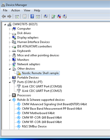
I am trying to test the nRF534 DK with my R&S CMW270 but i am not able to connect. i can see the Jlink ports but could not get a connection with either of them. I was able to program the DK to DTM mode using the nRF USB port but the CMW doesn't recognize it. It sees it as "Nordic Remote Shell sample." 

Do you a driver i can use or different instructions to use the CMW?

Parents
  • Hi Jesse,

    I am not exactly sure what the issue is.. I checked with my colleague again and was informed that the CMW should be fine with the com port by itself.. Could you make sure if you are using UART and not HCI.? This might also be an issue on the CMW side.. Could you also check with R&S if that's the case.?

    Regards,

    Swathy

  • Hi Swathy, 

    I was able to get the our 5340-DK working and now i can verify it is in DTM mode by using nRF Connect. my CMW270 also now recognizes it and I'm able to measure TX/RX. 

    I had to create a new build and reprogram it again but it seems to be working now. Maybe I didn't do it correctly the first time but I didn't get any errors when programming it. 

    But now I wanted to test my board that's using a nRF5340-CLAA, and I am running into the same issue. I have modified the nrf5340dk_cpuapp_common-pinctl.dtsi to the pins i want to communicate with. I'm using a 1.8 FTDI cable since we are using 1.8V to power the nRF5340. 

    But i can't get any communication and the nRF Connect DTM app doesn't see it. 

    below is how i set my UART lines to the desired pins on the "nrf5340dk_cpuapp_common-pinctl.dtsi":

        uart0_default: uart0_default {
            group1 {
                psels = <NRF_PSEL(UART_TX, 0, 27)>;
            };
            group2 {
                psels = <NRF_PSEL(UART_RX, 0, 28)>;
                bias-pull-up;
            };
        };

        uart0_sleep: uart0_sleep {
            group1 {
                psels = <NRF_PSEL(UART_TX, 0, 27)>,
                    <NRF_PSEL(UART_RX, 0, 28)>;
                low-power-enable;
            };
        };
  • Hi Jesse,

    You had problem with programming your DK with the DTM firmware.? make sure to clear the chip prior to programming it [ nrfjprog --recover] and it should work fine.. 

    JesB said:
    I was able to get the our 5340-DK working and now i can verify it is in DTM mode by using nRF Connect. my CMW270 also now recognizes it and I'm able to measure TX/RX. 

    Glad to know that it worked.

    Regards,

    Swathy

  • Hi Swathy,

    Yes, i was able to get out DK working. 

    But now i am working on my custom board. and we are using the nRF5340-CLAA. 

    I have program the DTM code to our custom board but i cannot communicate with the UART-DTM. 

    I have changed the defaults UART pins for my board but i don't get any communication from from it. I am using the nRFconnect DTM to verify communication. 

Reply
  • Hi Swathy,

    Yes, i was able to get out DK working. 

    But now i am working on my custom board. and we are using the nRF5340-CLAA. 

    I have program the DTM code to our custom board but i cannot communicate with the UART-DTM. 

    I have changed the defaults UART pins for my board but i don't get any communication from from it. I am using the nRFconnect DTM to verify communication. 

Children
  • Hi Swathy,

    I am still having issues using DTM on my custom board with the nRF5340. i have modified the cpuapp overlay to the TX/RX pins i have for UART but I still cant get any communication when trying to use the DTM in NRF Connect foe Desktop. Any suggestions?

    I have change the CPUapp overlay to 

    /*
     * Copyright (c) 2022 Nordic Semiconductor ASA
     *
     * SPDX-License-Identifier: LicenseRef-Nordic-5-Clause
     */

    / {
        chosen {
            zephyr,shell-ipc = &ipc0;
            ncs,remote-shell-uart = &uart0;
        };
    };

    &pinctrl {
        uart0_default: uart0_default {
            group1 {
                psels = <NRF_PSEL(UART_TX, 1, 7)>;
            };
            group2 {
                psels = <NRF_PSEL(UART_RX, 1, 8)>;
                bias-pull-up;
            };
        };

        uart0_sleep: uart0_sleep {
            group1 {
                psels = <NRF_PSEL(UART_TX, 1, 7)>,
                    <NRF_PSEL(UART_RX, 1, 8)>;
                low-power-enable;
            };
        };
    };

    &uart0 {
        status = "okay";
        current-speed = <19200>;
        pinctrl-0 = <&uart0_default>;
        pinctrl-1 = <&uart0_sleep>;
        pinctrl-names = "default", "sleep";
    };

    &gpio_fwd {
        dfe-radio {
            gpios = <&gpio0 4 0>,
            <&gpio0 5 0>,
            <&gpio0 6 0>,
            <&gpio0 7 0>;
        };
    };

    I have kept the cpunet overlay as

    / {
        chosen {
            ncs,dtm-uart = &uart0;
        };
    };

    &uart0 {
        status = "okay";
        compatible = "nordic,nrf-ipc-uart";
        ipc = <&ipc0>;
        ept-name = "remote shell";
        current-speed = <19200>;
    };


    &radio {
        status = "okay";
        /* This is a number of antennas that are available on antenna matrix
         * designed by Nordic. For more information see README.rst.
         */
        dfe-antenna-num = <12>;
        /* This is a setting that enables antenna 12 (in antenna matrix designed
         * by Nordic) for PDU. For more information see README.rst.
         */
        dfe-pdu-antenna = <0x0>;

        /* These are GPIO pin numbers that are provided to
         * Radio peripheral. The pins will be acquired by Radio to
         * drive antenna switching.
         * Pin numbers are selected to drive switches on antenna matrix
         * desinged by Nordic. For more information see README.rst.
         */
        dfegpio0-gpios = <&gpio0 4 0>;
        dfegpio1-gpios = <&gpio0 5 0>;
        dfegpio2-gpios = <&gpio0 6 0>;
        dfegpio3-gpios = <&gpio0 7 0>;
    };
     
Related