How much min. require sink current of nrf52832 gpio pin.

Hello, 

Scenario:-

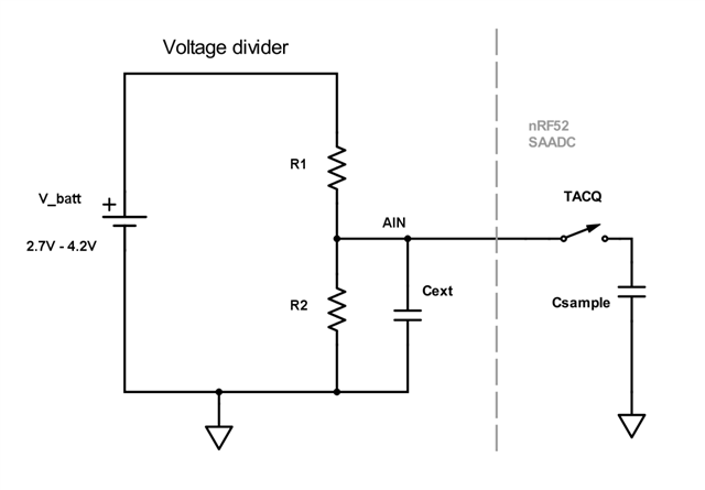
In our setup we used a voltage divider to detect the battery percentage.

For that we used R1= 1M and R2= 3.16M resistor.

Our problem:-

As output of the divider when battery voltage is 4.13v. Output should be 3.137v but we get 2.91v.

So here we get the voltage drop. So we think that because of the large resistor divider current going through the controller is very less like in uA.

Our conclusion:- 

So for less current going to the controller, they need current so that they suppress the output voltage to get the required current.

Can you specify how much current a gpio can operate? or any suggestion from your side for choosing the resistor.

Thanks in advance!!

Parents Reply
  • You need a capacitor close to the pin to compensate for the drop in voltage over the resistors when the ADC samples the pin. When you use very large resistors, you need to buffer the voltage with a capacitor. Else you will measure lower voltage. The internal cap in the ADC will load the pin. 

Children
  • Thanks for this details. Here I have only one qestion that what is reason behind the voltage drop across the resistor?

  • When the ADC starts sampling it will open the switch shown in the picture, TACQ. The Csample cap will charge through R1 for a short while. If the value of R1 is large, the cap won't be fully charged when the sampling is finished and the value you read with the ADC will be too low. If you have a external cap, Cext, this will slowly be charged through R1 so there's no voltage drop across R1 when the ADC samples. 

  • Thanks for the providing this details.