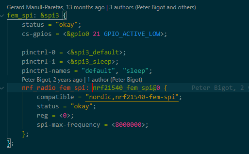
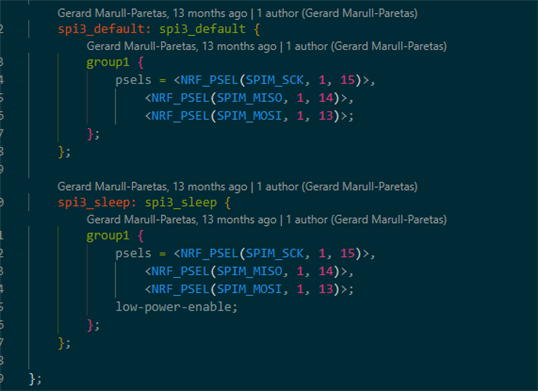
Radio test configuration nrf21540DK

Hi  

I am using nrf21540DK, NCS version 2.3.0Radio Test example, RSSI Viewer as a Scanner, and VSCODE studio as an IDE. 

I just come to know that. do not support the nrf21540DK configuration. I tested its RSSI and got -23dm @0 to 4 dbm input from nrf52840.

To confirm the communication between nrf21540 and nrf52840, I used an oscilloscope to monitor the SPI signals on P1.13, 14, and 15. But I got no signal.

After that when I loaded the supported "Direct test mode " example I got the pulses on these pins.

Can you please help me in this regard that how to make it work with the "Radio test" example? 
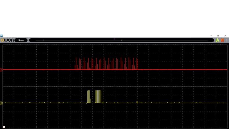
Above picture is when i tested it with Direct test mode.But no signals in case of radio test example.

Can you please help me in this regard? I tested my custom (nrf52833+nrf21540) board as well .And i faced the same issue with that as well.

Thanks & regards,

Muhammad Usman

Parents
  • Hi,

    Seems like you have gotten further but still struggling with the confirmation on the radio test.


    So for the custom board do you have easy access to all the pins on the nRF21540? It is possible to put the FEM in different modes by pulling pins high externally. 


    You can check pins from the nrf21540dk_nrf52840.dts file.


    So if you have a scope you can check ant select, PDN, mode and RX and TX as well. 


    using commands change the antenna or starting and stopping TX transmission should show the lines go high and low. 


    And for the SPI the pins you named are correct. 


    When you are building for the nrf21540DK and sett CONFIG_FEM=y it should work. 

    If you add CONFIG_RADIO_TEST_POWER_CONTROL_AUTOMATIC=n then you should be able to individually control the FEM gain as well. 


    With automatic control disabled:
    uart:~$ fem
    tx_gain antenna ramp_up_time

    With automatic control enabled:
    uart:~$ fem
    antenna ramp_up_time


    And you can sett it to just a number, dont need the posXdBm for the tx_gain command, only X will do. 

    I am setting up some testes for both the 833DK + nRF21540EK and the 21540DK and will provide you with some steps and the results tomorrow. 

    Regards,
    Jonathan

Reply
  • Hi,

    Seems like you have gotten further but still struggling with the confirmation on the radio test.


    So for the custom board do you have easy access to all the pins on the nRF21540? It is possible to put the FEM in different modes by pulling pins high externally. 


    You can check pins from the nrf21540dk_nrf52840.dts file.


    So if you have a scope you can check ant select, PDN, mode and RX and TX as well. 


    using commands change the antenna or starting and stopping TX transmission should show the lines go high and low. 


    And for the SPI the pins you named are correct. 


    When you are building for the nrf21540DK and sett CONFIG_FEM=y it should work. 

    If you add CONFIG_RADIO_TEST_POWER_CONTROL_AUTOMATIC=n then you should be able to individually control the FEM gain as well. 


    With automatic control disabled:
    uart:~$ fem
    tx_gain antenna ramp_up_time

    With automatic control enabled:
    uart:~$ fem
    antenna ramp_up_time


    And you can sett it to just a number, dont need the posXdBm for the tx_gain command, only X will do. 

    I am setting up some testes for both the 833DK + nRF21540EK and the 21540DK and will provide you with some steps and the results tomorrow. 

    Regards,
    Jonathan

Children
No Data
Related