Radio test configuration nrf21540DK

Hi  

I am using nrf21540DK, NCS version 2.3.0Radio Test example, RSSI Viewer as a Scanner, and VSCODE studio as an IDE. 

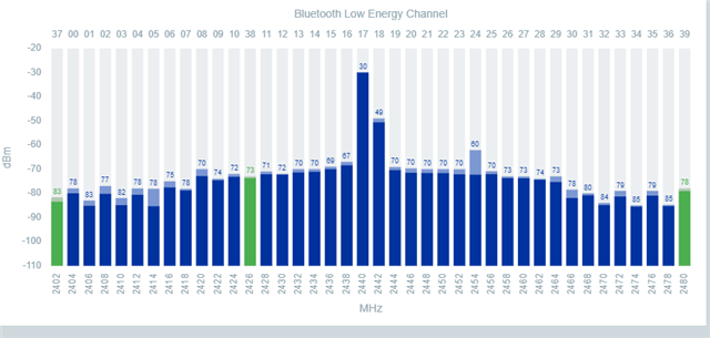
I just come to know that. do not support the nrf21540DK configuration. I tested its RSSI and got -23dm @0 to 4 dbm input from nrf52840.

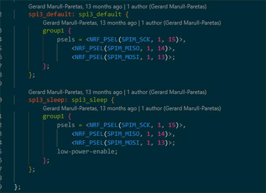
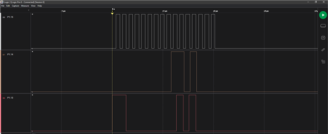
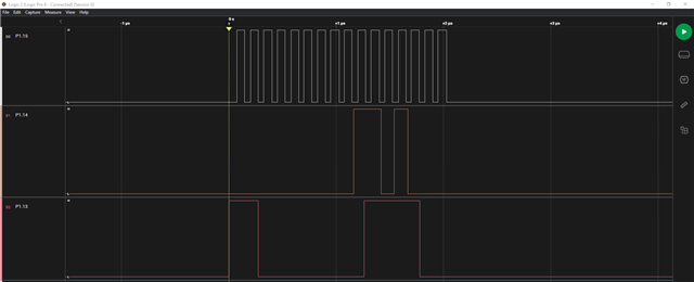
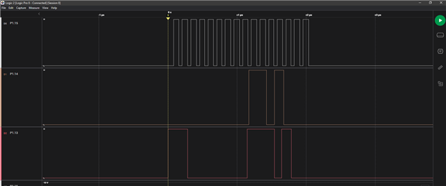
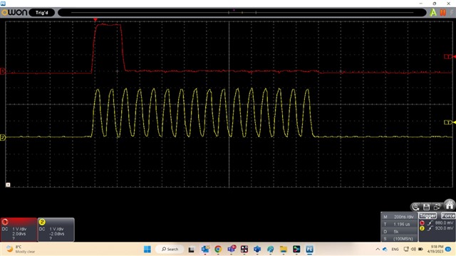
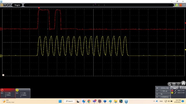
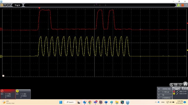
To confirm the communication between nrf21540 and nrf52840, I used an oscilloscope to monitor the SPI signals on P1.13, 14, and 15. But I got no signal.

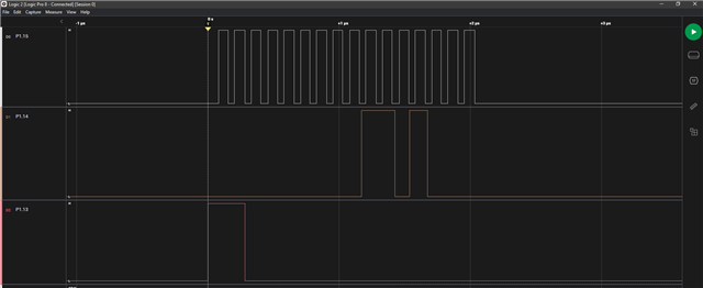
After that when I loaded the supported "Direct test mode " example I got the pulses on these pins.

Can you please help me in this regard that how to make it work with the "Radio test" example? 

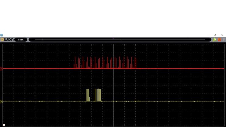
Above picture is when i tested it with Direct test mode.But no signals in case of radio test example.

Can you please help me in this regard? I tested my custom (nrf52833+nrf21540) board as well .And i faced the same issue with that as well.

Thanks & regards,

Muhammad Usman

  • Hi,

    Seems like you have gotten further but still struggling with the confirmation on the radio test.


    So for the custom board do you have easy access to all the pins on the nRF21540? It is possible to put the FEM in different modes by pulling pins high externally. 


    You can check pins from the nrf21540dk_nrf52840.dts file.


    So if you have a scope you can check ant select, PDN, mode and RX and TX as well. 


    using commands change the antenna or starting and stopping TX transmission should show the lines go high and low. 


    And for the SPI the pins you named are correct. 


    When you are building for the nrf21540DK and sett CONFIG_FEM=y it should work. 

    If you add CONFIG_RADIO_TEST_POWER_CONTROL_AUTOMATIC=n then you should be able to individually control the FEM gain as well. 


    With automatic control disabled:
    uart:~$ fem
    tx_gain antenna ramp_up_time

    With automatic control enabled:
    uart:~$ fem
    antenna ramp_up_time


    And you can sett it to just a number, dont need the posXdBm for the tx_gain command, only X will do. 

    I am setting up some testes for both the 833DK + nRF21540EK and the 21540DK and will provide you with some steps and the results tomorrow. 

    Regards,
    Jonathan

  • Update:

    Setup with the nRF21540DK, Radio test example, with the following configs:

    CONFIG_FEM=y

    CONFIG_RADIO_TEST_POWER_CONTROL_AUTOMATIC=n


    Using the Saleae logic pro to check the SPI lines. Connected to pin P1.13, P1.14 and P1.15 and I am able to see activity. 

    Picture above is captured when the start_tx_carrier command is send.

    uart:~$ output_power neg8dBm
    TX power: RADIO_TXPOWER_TXPOWER_Neg8dBm
    uart:~$ fem tx_gain 0
    Front-end module (FEM) Tx gain set to 0
    uart:~$ start_channel 40
    Start channel set to: 40
    uart:~$ start_tx_carrier
    Requested tx output power: -8 dBm
    Tx output power set to: -8 dBm
    Start the TX carrier


    This capture is with the below commands, capture is taken when tx_carrier command is sent. 


    uart:~$ fem tx_gain 10
    Front-end module (FEM) Tx gain set to 10
    uart:~$ start_tx_carrier
    Requested tx output power: -8 dBm
    Tx output power set to: -8 dBm
    Start the TX carrier
    uart:~$


    There is no activity on the SPI lines before the start tx is sent.


    Here is a test where automatic power control was enabled


    uart:~$ output_power neg12dBm
    TX power: RADIO_TXPOWER_TXPOWER_Neg12dBm
    uart:~$ start_tx_carrier
    Requested tx output power: -12 dBm
    Tx output power set to: -30 dBm
    Start the TX carrier
    uart:~$


    For the nrf52833DK with the 21540EK:

    SPI works here as well, you can see that there is the same type of action on the different SPI pins here:


    uart:~$ start_channel 40
    Start channel set to: 40
    uart:~$ start_tx_carrier
    Requested tx output power: 20 dBm
    Tx output power set to: 20 dBm
    Start the TX carrier
    uart:~$


    I have also used a nRF52DK connected to RSSI viewer app to confirm that the DUT is transmitting. 

    Regards,
    Jonathan

  • Hi  

    Thank you so much for your great support. I really appreciate the efforts you did for me.

    I will test soon and update you as well about the results on my end.

    Thanks & Regards,

    Muhammad Usman

  • Hi  

    Again thank you for the response!

    Today I tested as per your instructions.

    CLK and MOSI P1.13, when gain Set to 0 for FEM (nrf21540 DK)

    CLK and MISO P1.14 ,when gain Set to 0 for FEM(nrf21540 DK)

    CLK and MOSI P1.13, when gain Set to 10 for FEM(nrf21540 DK)

    CLK and MISO P1.14. when gain Set to 10 for FEM(nrf21540 DK)

    So for the custom board do you have easy access to all the pins on the nRF21540?

    Sorry in the current version of the custom board (nrf52833+nrf21540), we don't have easy access to all pins.

    So can we confirm that nrf21450 is working fine via external Registers using SPI communication? Or do you have any better suggestion to ensure communication other than RSSI value? 

    To confirm that the radio test example pin configuration is mapped correctly and will work fine for the custom board. We tested FW on the nrf52833 DK and monitored the Clk and MOSI signals on that. We are getting the same waveform as pasted above for nrf21540 Dk.

    Thanks & regards,

    Muhammad Usman

  • Muhammad Usman said:
    So can we confirm that nrf21450 is working fine via external Registers using SPI communication?

    You can check by reading a register of the nRF21540 over SPI yes, but I don't think we have any samples for that. 

    So you can use Read from CONREG0 or 1 if you want to confirm that what you think you have been writing to the FEM is what you think it is after you sett whatever write. Or you can just read any readable register to confirm that SPI is working. 

    https://infocenter.nordicsemi.com/topic/ps_nrf21540/chapters/device_control/doc/operating_state.html?cp=8_0_0_4_0 


    https://infocenter.nordicsemi.com/topic/ps_nrf21540/chapters/spi/doc/frontpage.html?cp=8_0_0_5 


    If you need any more help on confirming that you are doing it correctly then just update me here and I will try to make a better example. 


    Muhammad Usman said:
    To confirm that the radio test example pin configuration is mapped correctly and will work fine for the custom board. We tested FW on the nrf52833 DK and monitored the Clk and MOSI signals on that. We are getting the same waveform as pasted above for nrf21540 Dk.

    This should be sufficient to confirm that it works. But if the custom board is not performing as expected and the DK is working fine then there might be something HW related. IF so then we can try to help with that as well

    Regards,
    Jonathan

Related