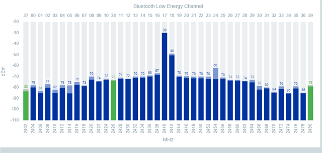
Radio test configuration nrf21540DK

Hi  

I am using nrf21540DK, NCS version 2.3.0Radio Test example, RSSI Viewer as a Scanner, and VSCODE studio as an IDE. 

I just come to know that. do not support the nrf21540DK configuration. I tested its RSSI and got -23dm @0 to 4 dbm input from nrf52840.

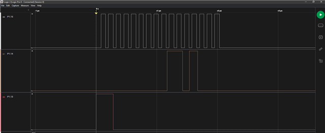
To confirm the communication between nrf21540 and nrf52840, I used an oscilloscope to monitor the SPI signals on P1.13, 14, and 15. But I got no signal.

After that when I loaded the supported "Direct test mode " example I got the pulses on these pins.

Can you please help me in this regard that how to make it work with the "Radio test" example? 
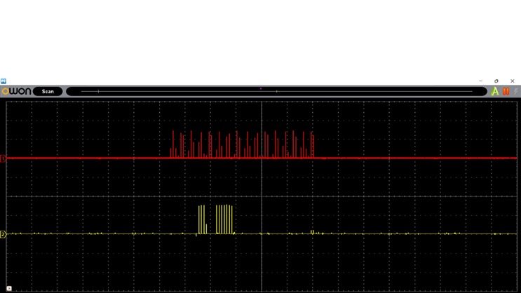
Above picture is when i tested it with Direct test mode.But no signals in case of radio test example.

Can you please help me in this regard? I tested my custom (nrf52833+nrf21540) board as well .And i faced the same issue with that as well.

Thanks & regards,

Muhammad Usman

Parents
  • Update:

    Setup with the nRF21540DK, Radio test example, with the following configs:

    CONFIG_FEM=y

    CONFIG_RADIO_TEST_POWER_CONTROL_AUTOMATIC=n


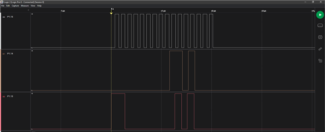
    Using the Saleae logic pro to check the SPI lines. Connected to pin P1.13, P1.14 and P1.15 and I am able to see activity. 

    Picture above is captured when the start_tx_carrier command is send.

    uart:~$ output_power neg8dBm
    TX power: RADIO_TXPOWER_TXPOWER_Neg8dBm
    uart:~$ fem tx_gain 0
    Front-end module (FEM) Tx gain set to 0
    uart:~$ start_channel 40
    Start channel set to: 40
    uart:~$ start_tx_carrier
    Requested tx output power: -8 dBm
    Tx output power set to: -8 dBm
    Start the TX carrier


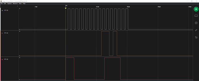
    This capture is with the below commands, capture is taken when tx_carrier command is sent. 


    uart:~$ fem tx_gain 10
    Front-end module (FEM) Tx gain set to 10
    uart:~$ start_tx_carrier
    Requested tx output power: -8 dBm
    Tx output power set to: -8 dBm
    Start the TX carrier
    uart:~$


    There is no activity on the SPI lines before the start tx is sent.


    Here is a test where automatic power control was enabled


    uart:~$ output_power neg12dBm
    TX power: RADIO_TXPOWER_TXPOWER_Neg12dBm
    uart:~$ start_tx_carrier
    Requested tx output power: -12 dBm
    Tx output power set to: -30 dBm
    Start the TX carrier
    uart:~$


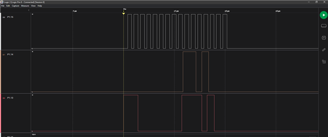
    For the nrf52833DK with the 21540EK:

    SPI works here as well, you can see that there is the same type of action on the different SPI pins here:


    uart:~$ start_channel 40
    Start channel set to: 40
    uart:~$ start_tx_carrier
    Requested tx output power: 20 dBm
    Tx output power set to: 20 dBm
    Start the TX carrier
    uart:~$


    I have also used a nRF52DK connected to RSSI viewer app to confirm that the DUT is transmitting. 

    Regards,
    Jonathan

  • Hi  

    Thank you so much for your great support. I really appreciate the efforts you did for me.

    I will test soon and update you as well about the results on my end.

    Thanks & Regards,

    Muhammad Usman

Reply Children
No Data
Related