Interrupt routine not working as intended. Did I do setup wrong?

Hello. I have a custom board with a digital sensor that gives a data-packet once every 8 seconds approximately. I have set up my code to enter an interrupt when a positive flank is received from the sensor. After the datapacket has been read, the receiving GPIO is first set to low output for 0.5 seconds and then set to high impedance input. After that I want the NRF to wait for the next positive flank on this GPIO from the sensor.

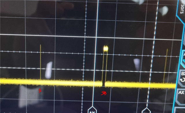
This seems to work for the most part. But sometimes, seemingly random, the NRF doesn't react on the received positive flank, and the NRF stays in the background-while loop. In the picture below I have measured on the GPIO which receives the data packet. On the left there is a data-packet which the ISR reacted on correctly. But for the next positive flank, the NRF did nothing. I suspect there is something wrong with my interrupt setup.

Below you can check my setup code for the interrupt. Is there anything you can see that is wrong or missing?

void in_pin_handler(nrf_drv_gpiote_pin_t pin, nrf_gpiote_polarity_t action)
{

    
    nrf_drv_gpiote_in_event_disable(PIN_IN);

    nrf_drv_gpiote_in_uninit(PIN_IN);

    readlowpowerpyro(); // Read data packet from sensor
 
    nrf_drv_gpiote_in_config_t in_config = GPIOTE_CONFIG_IN_SENSE_LOTOHI(true);
    in_config.pull = NRF_GPIO_PIN_NOPULL;

    ret_code_t err_code = nrf_drv_gpiote_in_init(PIN_IN, &in_config, in_pin_handler);
    APP_ERROR_CHECK(err_code);

    nrf_drv_gpiote_in_event_enable(PIN_IN, true);
    

  //  __WFE();
  //  __SEV();
  // __WFE();

}

static void gpio_init(void)
{
    ret_code_t err_code;

    err_code = nrf_drv_gpiote_init();
    APP_ERROR_CHECK(err_code);

    nrf_drv_gpiote_in_config_t in_config = GPIOTE_CONFIG_IN_SENSE_LOTOHI(true);
    in_config.pull = NRF_GPIO_PIN_NOPULL;

    err_code = nrf_drv_gpiote_in_init(PIN_IN, &in_config, in_pin_handler);
    APP_ERROR_CHECK(err_code);

    nrf_drv_gpiote_in_event_enable(PIN_IN, true);
}

Here is the code for setting the GPIO to low output for 0.5 seconds and then to high impedance, making it ready to receive the next datapacket.

  nrf_gpio_pin_clear(PIN_IN);
  nrf_gpio_cfg_output(PIN_IN);
  nrf_delay_us(500);
  nrf_gpio_cfg_input(PIN_IN,NRF_GPIO_PIN_NOPULL);

Parents
  • When the interrupt routine is not reacting on the postive flank I tried manually doing the ISR operations inside of the background while-loop. So I added this code to the while-loop with an if-statement: 

    while()
    {
      
      if(PIN_IN)
      {
      
      nrf_drv_gpiote_in_event_disable(PIN_IN);
    
        nrf_drv_gpiote_in_uninit(PIN_IN);
    
        readlowpowerpyro(); // Read data packet from sensor
     
        nrf_drv_gpiote_in_config_t in_config = GPIOTE_CONFIG_IN_SENSE_LOTOHI(true);
        in_config.pull = NRF_GPIO_PIN_NOPULL;
    
        ret_code_t err_code = nrf_drv_gpiote_in_init(PIN_IN, &in_config, in_pin_handler);
        APP_ERROR_CHECK(err_code);
    
        nrf_drv_gpiote_in_event_enable(PIN_IN, true);
        
        }
    }

    This makes it come out of the stuck state. But I want to find the issue with my ISR. The plan is later on to use the interrupt event to wake the NRF from low power mode.

    Below is the GPIO with the added code to the while-loop. Normal ISR to the left, While-loop operations to the right (when the ISR fails to act).

Reply
  • When the interrupt routine is not reacting on the postive flank I tried manually doing the ISR operations inside of the background while-loop. So I added this code to the while-loop with an if-statement: 

    while()
    {
      
      if(PIN_IN)
      {
      
      nrf_drv_gpiote_in_event_disable(PIN_IN);
    
        nrf_drv_gpiote_in_uninit(PIN_IN);
    
        readlowpowerpyro(); // Read data packet from sensor
     
        nrf_drv_gpiote_in_config_t in_config = GPIOTE_CONFIG_IN_SENSE_LOTOHI(true);
        in_config.pull = NRF_GPIO_PIN_NOPULL;
    
        ret_code_t err_code = nrf_drv_gpiote_in_init(PIN_IN, &in_config, in_pin_handler);
        APP_ERROR_CHECK(err_code);
    
        nrf_drv_gpiote_in_event_enable(PIN_IN, true);
        
        }
    }

    This makes it come out of the stuck state. But I want to find the issue with my ISR. The plan is later on to use the interrupt event to wake the NRF from low power mode.

    Below is the GPIO with the added code to the while-loop. Normal ISR to the left, While-loop operations to the right (when the ISR fails to act).

Children
No Data
Related