Interrupt routine not working as intended. Did I do setup wrong?

Hello. I have a custom board with a digital sensor that gives a data-packet once every 8 seconds approximately. I have set up my code to enter an interrupt when a positive flank is received from the sensor. After the datapacket has been read, the receiving GPIO is first set to low output for 0.5 seconds and then set to high impedance input. After that I want the NRF to wait for the next positive flank on this GPIO from the sensor.

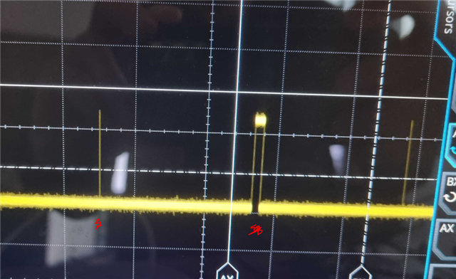
This seems to work for the most part. But sometimes, seemingly random, the NRF doesn't react on the received positive flank, and the NRF stays in the background-while loop. In the picture below I have measured on the GPIO which receives the data packet. On the left there is a data-packet which the ISR reacted on correctly. But for the next positive flank, the NRF did nothing. I suspect there is something wrong with my interrupt setup.

Below you can check my setup code for the interrupt. Is there anything you can see that is wrong or missing?

void in_pin_handler(nrf_drv_gpiote_pin_t pin, nrf_gpiote_polarity_t action)
{

    
    nrf_drv_gpiote_in_event_disable(PIN_IN);

    nrf_drv_gpiote_in_uninit(PIN_IN);

    readlowpowerpyro(); // Read data packet from sensor
 
    nrf_drv_gpiote_in_config_t in_config = GPIOTE_CONFIG_IN_SENSE_LOTOHI(true);
    in_config.pull = NRF_GPIO_PIN_NOPULL;

    ret_code_t err_code = nrf_drv_gpiote_in_init(PIN_IN, &in_config, in_pin_handler);
    APP_ERROR_CHECK(err_code);

    nrf_drv_gpiote_in_event_enable(PIN_IN, true);
    

  //  __WFE();
  //  __SEV();
  // __WFE();

}

static void gpio_init(void)
{
    ret_code_t err_code;

    err_code = nrf_drv_gpiote_init();
    APP_ERROR_CHECK(err_code);

    nrf_drv_gpiote_in_config_t in_config = GPIOTE_CONFIG_IN_SENSE_LOTOHI(true);
    in_config.pull = NRF_GPIO_PIN_NOPULL;

    err_code = nrf_drv_gpiote_in_init(PIN_IN, &in_config, in_pin_handler);
    APP_ERROR_CHECK(err_code);

    nrf_drv_gpiote_in_event_enable(PIN_IN, true);
}

Here is the code for setting the GPIO to low output for 0.5 seconds and then to high impedance, making it ready to receive the next datapacket.

  nrf_gpio_pin_clear(PIN_IN);
  nrf_gpio_cfg_output(PIN_IN);
  nrf_delay_us(500);
  nrf_gpio_cfg_input(PIN_IN,NRF_GPIO_PIN_NOPULL);

  • When the interrupt routine is not reacting on the postive flank I tried manually doing the ISR operations inside of the background while-loop. So I added this code to the while-loop with an if-statement: 

    while()
    {
      
      if(PIN_IN)
      {
      
      nrf_drv_gpiote_in_event_disable(PIN_IN);
    
        nrf_drv_gpiote_in_uninit(PIN_IN);
    
        readlowpowerpyro(); // Read data packet from sensor
     
        nrf_drv_gpiote_in_config_t in_config = GPIOTE_CONFIG_IN_SENSE_LOTOHI(true);
        in_config.pull = NRF_GPIO_PIN_NOPULL;
    
        ret_code_t err_code = nrf_drv_gpiote_in_init(PIN_IN, &in_config, in_pin_handler);
        APP_ERROR_CHECK(err_code);
    
        nrf_drv_gpiote_in_event_enable(PIN_IN, true);
        
        }
    }

    This makes it come out of the stuck state. But I want to find the issue with my ISR. The plan is later on to use the interrupt event to wake the NRF from low power mode.

    Below is the GPIO with the added code to the while-loop. Normal ISR to the left, While-loop operations to the right (when the ISR fails to act).

  • Hi,

    I'm not sure I follow correctly the flow of your application. Could you include the full main.c file for better understanding?

    Do you use the same pin for interrupt and for reading the datapacket, and for outputting a signal?

    Are you testing this with a minimal application, without any other peripherals running, or could there be some other interrupt handling preventing/delaying the handling of the pin interrupt?

    if(PIN_IN) will always be true, since this is the pin number (which is higher than zero). If your intention was to read the pin state, you need to use the nrf_drv_gpiote_in_is_set() API or similar GPIO HAL function.

    Best regards,
    Jørgen

  • Sorry for being unclear. Here is the whole code.

    Yes, I am using the same GPIO to detect a positive flank and reading the datapacket. The oscilloscope pictures above is the GPIO that detects the positive flank and also reads the datapacket (the data can be seen if I zoom in on the oscilloscope).

    Yes it is a minimal application. 

    Yes, I made a mistake in the previous post. In the code I used if(nrf_gpio_pin_read(PIN_IN)), not if(PIN_IN)

    /**
     * Copyright (c) 2014 - 2019, Nordic Semiconductor ASA
     *
     * All rights reserved.
     *
     * Redistribution and use in source and binary forms, with or without modification,
     * are permitted provided that the following conditions are met:
     *
     * 1. Redistributions of source code must retain the above copyright notice, this
     *    list of conditions and the following disclaimer.
     *
     * 2. Redistributions in binary form, except as embedded into a Nordic
     *    Semiconductor ASA integrated circuit in a product or a software update for
     *    such product, must reproduce the above copyright notice, this list of
     *    conditions and the following disclaimer in the documentation and/or other
     *    materials provided with the distribution.
     *
     * 3. Neither the name of Nordic Semiconductor ASA nor the names of its
     *    contributors may be used to endorse or promote products derived from this
     *    software without specific prior written permission.
     *
     * 4. This software, with or without modification, must only be used with a
     *    Nordic Semiconductor ASA integrated circuit.
     *
     * 5. Any software provided in binary form under this license must not be reverse
     *    engineered, decompiled, modified and/or disassembled.
     *
     * THIS SOFTWARE IS PROVIDED BY NORDIC SEMICONDUCTOR ASA "AS IS" AND ANY EXPRESS
     * OR IMPLIED WARRANTIES, INCLUDING, BUT NOT LIMITED TO, THE IMPLIED WARRANTIES
     * OF MERCHANTABILITY, NONINFRINGEMENT, AND FITNESS FOR A PARTICULAR PURPOSE ARE
     * DISCLAIMED. IN NO EVENT SHALL NORDIC SEMICONDUCTOR ASA OR CONTRIBUTORS BE
     * LIABLE FOR ANY DIRECT, INDIRECT, INCIDENTAL, SPECIAL, EXEMPLARY, OR
     * CONSEQUENTIAL DAMAGES (INCLUDING, BUT NOT LIMITED TO, PROCUREMENT OF SUBSTITUTE
     * GOODS OR SERVICES; LOSS OF USE, DATA, OR PROFITS; OR BUSINESS INTERRUPTION)
     * HOWEVER CAUSED AND ON ANY THEORY OF LIABILITY, WHETHER IN CONTRACT, STRICT
     * LIABILITY, OR TORT (INCLUDING NEGLIGENCE OR OTHERWISE) ARISING IN ANY WAY OUT
     * OF THE USE OF THIS SOFTWARE, EVEN IF ADVISED OF THE POSSIBILITY OF SUCH DAMAGE.
     *
     */
    /** @file
     * @defgroup pin_change_int_example_main main.c
     * @{
     * @ingroup pin_change_int_example
     * @brief Pin Change Interrupt Example Application main file.
     *
     * This file contains the source code for a sample application using interrupts triggered by GPIO pins.
     *
     */
    #include <stdbool.h>
    #include <stdint.h>
    #include "nrf_delay.h"
    #include "boards.h"
    #include "nrf_gpio.h"
    #include "nrf.h"
    #include "nrf_drv_gpiote.h"
    #include "app_error.h"
    
    
    #define PIN_IN 16 //DL, tidigare 11
    #define LED 14 // tidigare 14   
    #define SI_pin 12   //SI, tidigare 13
    #define SensorTurnOn 18
    
    int PIRval = 0; // PIR signal 
    unsigned long statcfg = 0; // status and configuration register 
    int k;
    
    void writeregval(unsigned long regval);
    unsigned long regval1;
    
    void readlowpowerpyro(void);
    
    
    void in_pin_handler(nrf_drv_gpiote_pin_t pin, nrf_gpiote_polarity_t action)
    {
    
        
        nrf_drv_gpiote_in_event_disable(PIN_IN);
    
        nrf_drv_gpiote_in_uninit(PIN_IN);
    
        readlowpowerpyro(); // Read data packet from sensor
           
           nrf_gpio_pin_set(LED);
           nrf_delay_ms(1000);
           nrf_gpio_pin_clear(LED);
           nrf_delay_ms(1000);
    
        nrf_drv_gpiote_in_config_t in_config = GPIOTE_CONFIG_IN_SENSE_LOTOHI(true);
        in_config.pull = NRF_GPIO_PIN_NOPULL;
    
        ret_code_t err_code = nrf_drv_gpiote_in_init(PIN_IN, &in_config, in_pin_handler);
        APP_ERROR_CHECK(err_code);
    
        nrf_drv_gpiote_in_event_enable(PIN_IN, true);
        
    
      //  __WFE();
      //  __SEV();
      // __WFE();
    
    }
    
    static void gpio_init(void)
    {
        ret_code_t err_code;
    
        err_code = nrf_drv_gpiote_init();
        APP_ERROR_CHECK(err_code);
    
        nrf_drv_gpiote_in_config_t in_config = GPIOTE_CONFIG_IN_SENSE_LOTOHI(true);
        in_config.pull = NRF_GPIO_PIN_NOPULL;
    
        err_code = nrf_drv_gpiote_in_init(PIN_IN, &in_config, in_pin_handler);
        APP_ERROR_CHECK(err_code);
    
        nrf_drv_gpiote_in_event_enable(PIN_IN, true);
    }
    
    /**
     * @brief Function for application main entry.
     */
    int main(void)
    {
        
        nrf_gpio_cfg_output(SensorTurnOn);
        nrf_gpio_pin_set(SensorTurnOn);
    
       // regval1 = 0x01711;
          regval1
        = 0x1EE111;
        writeregval(regval1);
        nrf_gpio_cfg_input(PIN_IN,NRF_GPIO_PIN_NOPULL);


        gpio_init();
    
        while (true)
        {     
    
         if(nrf_gpio_pin_read(PIN_IN))
           { 
               
        nrf_drv_gpiote_in_uninit(PIN_IN);
    
        readlowpowerpyro();
    
        nrf_gpio_pin_set(LED);
        nrf_delay_ms(1000);
        nrf_gpio_pin_clear(LED);
        nrf_delay_ms(1000);
      
        ret_code_t err_code;
    
        err_code = nrf_drv_gpiote_init();
    
        nrf_drv_gpiote_in_config_t in_config = GPIOTE_CONFIG_IN_SENSE_LOTOHI(true);
        in_config.pull = NRF_GPIO_PIN_NOPULL;
    
        err_code = nrf_drv_gpiote_in_init(PIN_IN, &in_config, in_pin_handler);
        APP_ERROR_CHECK(err_code);
    
        nrf_drv_gpiote_in_event_enable(PIN_IN, true);
            
           } 
    
          }
        
          
        }


    void readlowpowerpyro(void) {
     
    
     int i; 
     unsigned int uibitmask; 
     unsigned long ulbitmask; 
    
     nrf_delay_us(140);  
     
     // get first 15bit out-off-range and ADC value 
     uibitmask = 0x4000; // Set BitPos 
     PIRval = 0; 
     for (i=0; i < 15; i++) 
     { 
    
    
     nrf_gpio_pin_clear(PIN_IN);
     nrf_gpio_cfg_output(PIN_IN);
     //nrf_delay_us(10);
     nrf_gpio_pin_set(PIN_IN);
     //nrf_delay_us(10);


     nrf_gpio_cfg_input(PIN_IN,NRF_GPIO_PIN_NOPULL);
     //nrf_delay_us(1);
    
     if(nrf_gpio_pin_read(PIN_IN)) PIRval |= uibitmask;
     uibitmask = uibitmask >> 1;
     //nrf_gpio_cfg_output(DL_pin);
    
     } 
    
     // get 25bit status and config 
     ulbitmask = 0x1000000; // Set BitPos 
     statcfg = 0; 
     for (i=0; i < 25; i++) 
     { 
     // create low to high transition 
     nrf_gpio_pin_clear(PIN_IN);
     nrf_gpio_cfg_output(PIN_IN);
     //nrf_delay_us(1);
     //nrf_gpio_pin_set(DL_pin);
     nrf_gpio_pin_toggle(PIN_IN);
     //nrf_delay_us(1);
    
     nrf_gpio_cfg_input(PIN_IN,NRF_GPIO_PIN_NOPULL);
     //nrf_delay_us(1);
    
     if(nrf_gpio_pin_read(PIN_IN)) statcfg  |= ulbitmask;
     ulbitmask = ulbitmask >> 1;
    
     }
    
      nrf_gpio_pin_clear(PIN_IN);
      nrf_gpio_cfg_output(PIN_IN);
      nrf_delay_us(500);
      nrf_gpio_cfg_input(PIN_IN,NRF_GPIO_PIN_NOPULL);
     
    
    } 
    
    void writeregval(unsigned long regval){ 
    
    int i; 
    unsigned char nextbit; 
    unsigned long regmask = 0x01000000; 
    unsigned long compare = 0x0; 
    
    nrf_gpio_cfg_output(PIN_IN);
    nrf_gpio_cfg_output(SI_pin);
    
    nrf_gpio_pin_clear(PIN_IN);
    nrf_gpio_pin_clear(SI_pin);
     
     for(i=0;i < 25;i++){ 
    
     nrf_gpio_pin_clear(SI_pin); 
     nrf_gpio_pin_set(SI_pin);
     compare=regval&regmask;
    
     if(compare == 0)
      nrf_gpio_pin_clear(SI_pin);
      else
        nrf_gpio_pin_set(SI_pin); 
    
     regmask = regmask >> 1; 
     nrf_delay_us(120);
    
     }
    
     nrf_gpio_pin_clear(SI_pin);  
     regmask = 0x01000000;
     nrf_delay_us(650);
    
    }


    /** @} */
    

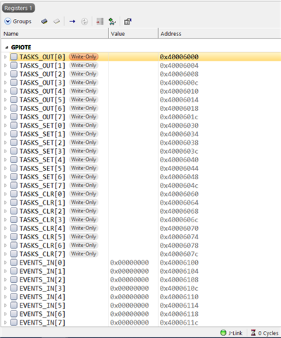
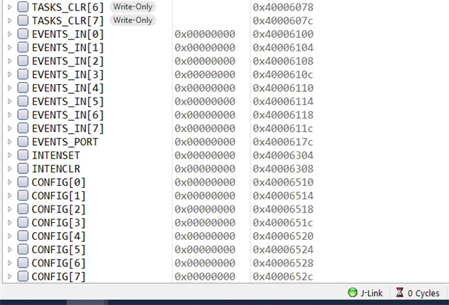
  • Can you read out the values of the GPIO and GPIOTE peripheral registers when this issue occurs?

    When this happens, are you stuck in the state where the interrupt does not happen if a new pulse is generated on the input, or will the issue resort itself after some time?

    I could not see any obvious issues in the code (apart from the unnecessary call to nrf_drv_gpiote_init() inside if(nrf_gpio_pin_read(PIN_IN)) where the return code is not checked, but since this is not part of your original code, I do not expect this to be an issue).

  • When it happens I am stuck in this state until i have performed "nrf_drv_gpiote_in_uninit(PIN_IN);" inside of the while-loop. If I dont do "nrf_drv_gpiote_in_uninit(PIN_IN);" then the GPIO stays high forever since the positive flank (from the sensor) has set the GPIO high, and the GPIO is stuck in its "high Z state". 

    I cant see the GPIO registers during debug for some reason. Here are the GPIOTE registers:

Related