nRF21540 SPI Gain Dynamic Control

Hi there,

Does the nRF Connect SDK support configuring the nRF21540 gain using SPI for values other than +10 and +20?

Looking at this previous Devzone question (SPI bus need to be dedicated to nRF21540?) it is mentioned that only GPIO-based gain setting is supported, which I believe restricts you to only +10 or +20. Although, this response was 1 year ago.

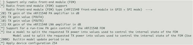
I am using the nRF21540-DK with the following KConfig options.

I am setting the Tx power (at the antenna) with the following piece of code on the Nordic DevZone. As you can see, this code also prints out what the FEM gain was set to after the Tx power has been set. Note: it seems a delay is required before querying the FEM gain or else the value will not be updated yet.

void set_tx_power(uint8_t handle_type, uint16_t handle, int8_t tx_pwr_lvl)
{
	struct bt_hci_cp_vs_write_tx_power_level *cp;
	struct bt_hci_rp_vs_write_tx_power_level *rp;
	struct net_buf *buf, *rsp = NULL;
	int err;

	buf = bt_hci_cmd_create(BT_HCI_OP_VS_WRITE_TX_POWER_LEVEL, sizeof(*cp));
	if(!buf) {
		__ASSERT_NO_MSG(false);
		return;
	}

	cp = net_buf_add(buf, sizeof(*cp));
	cp->handle = sys_cpu_to_le16(handle);
	cp->handle_type = handle_type;
	cp->tx_power_level = tx_pwr_lvl;

	err = bt_hci_cmd_send_sync(BT_HCI_OP_VS_WRITE_TX_POWER_LEVEL, buf, &rsp);
	if(err) {
		uint8_t reason =
			rsp ? ((struct bt_hci_rp_vs_write_tx_power_level *)rsp->data)->status : 0;
		__ASSERT(false, "Set Tx power err: %d reason 0x%02x\n", err, reason);
		return;
	}

	k_sleep(K_MSEC(100));
	int8_t gain = 0;
	mpsl_fem_pa_is_configured(&gain);

	rp = (void *)rsp->data;
	LOG_INF("New Tx Power: %d (Gain: %d)", rp->selected_tx_power, gain);

	net_buf_unref(rsp);
}

When I iterate through all of the potential Tx values from -20 to +20, the FEM Gain only ever changes between 10 and 20, it is not set to anything more granular. I believe when enabling configuration through SPI + using the Nordic power module, the FEM fain gain should be set to more granular values? This results in Tx power at the antenna that is off by 3dBm or more.

I can confirm that this file is being compiled, so it looks like it may be correctly using SPI:

nrf/subsys/mpsl/fem/nrf21540_gpio_spi/mpsl_fem_nrf21540_gpio_spi.c

My questions are:

  1. Should I expect to see FEM gain values other than +10 and +20?
  2. Is my method of setting the Tx power "at the antenna" correct?
  3. Is my method of querying the current gain of the FEM correct? It seems strange that it requires a delay beforehand. I followed this API down and it looks like it reads from a cached value in the stack rather than querying the FEM register directly, which doesn't fill me with as much confidence that it is accurate.

Thanks,

Sean

Parents
  • Update: This reply incorrectly says that the nRF21540 Gain cannot be finely controlled via the SPI interface.
    That is not the case. The nRF21540 Gain can be finely controlled via the SPI interface. However, there are some caveats. Please read the full discussion.

    Hi Sean,

    Should I expect to see FEM gain values other than +10 and +20?

    The nRF21540 can only switch between the two output power levels POUTA and POUTB. The +10 dB and +20 dB gain you observed are the production default value of these two levels.

    The value of POUTA and POUTB can be configured by writing to the CONFREG2 and CONFREG3 registers. However, they are one time programmable, and as such is not fit to be use in runtime.

    It is for this reason that a more granular control of the TX Power is not possible. Only combinations of POUTA or POUTB and the SoC's TX power can be achieved.

    Please also note that the nRF21540 also has a max output power of 22 dBm, even when the sum of SoC TX Power and FEM TX Gain is higher.

    Is my method of setting the Tx power "at the antenna" correct?

    I will need to double check on the HCI command. However, given the fact that you see a change in FEM Gain, it might be correct. To be sure, can you also look at the TXPOWER register, to see if it changes with each call of your function?

    You mentioned that you refer it from DevZone. May I ask for the source?

    Is my method of querying the current gain of the FEM correct? It seems strange that it requires a delay beforehand. I followed this API down and it looks like it reads from a cached value in the stack rather than querying the FEM register directly, which doesn't fill me with as much confidence that it is accurate.

    According to the documentation, it is correct. Could you please give some more details about the "reads from a cached value" part? From what cache is the gain fetched, and why would that make you doubtful?

    Hieu

  • Hi Hieu,

    I don't think your reply is correct, the nRF21540 gain can be set to values other than +10 and +20.

    The nRF21540 has a Tx Gain register that is writable over SPI to set the gain at more granular values, separate from the values found in UICR. Several other DevZone questions confirm this is possible. The Nordic radio_test sample also allows you to configure the FEM Gain register.

    When I set the power through the API described above, these are the selected tx powers that I receive.

    As you can see, it does not look like the nRF Connect SDK is correctly using the 1dB resolution of the Tx Gain register but is defaulting to using the MODE pin/register.

    Request Tx power Selected Tx Power
    -40 -30
    -20 -30
    -16 -30
    -12 -30
    -8 -10
    -4 -6
    0 -2
    -2 2
    4 2
    6 6
    8 6
    10 10
    12 12
    14 12
    16 16
    18 16
    20 20

    I should be able to achieve a Tx power closer to the requested Tx power if the nRF Connect SDK FEM driver is correctly using the Tx Gain register.

    Is there something in my configuration I am doing wrong?

  • Hi Sean,

    You are right. I can't believe how I missed the TX_GAIN bits in CONFREG0. Let me check with MPSL/FEM engineers and get back to you soon.

  • Hi Sean,

    MPSL controls the FEM using power models (see more about power model here).

    The default power model is setup so that the FEM gain is as close to +10 dB and +20 dB as possible. The FEM gain can be influenced by variations of voltage, temperature, and signal frequency; and MPSL uses the TX_GAIN register to tweak the gain to compensate for such influences.

    mpsl_fem_pa_is_configured() only gives you +10 and +20 dB depends on what the "target" TX gain is. The "configured" gain in the nRF21540 can be the same value, but could also be different. 

    To find out the actual configured TX gain value, you will need to read the TX_GAIN register. I am not sure how complicated it would be to setup, as MPSL otherwise has control over the SPI interface.

    If you wish for a different FEM control strategy, it is also possible to implement your own power model. Please note that the gain is not calibrated, so when you set the FEM to a particular TX gain, the FEM will only actually achieve an approximate of the desired value. 

    I hope this explanation satisfies you. My apology for the incorrect information in my first reply.

Reply
  • Hi Sean,

    MPSL controls the FEM using power models (see more about power model here).

    The default power model is setup so that the FEM gain is as close to +10 dB and +20 dB as possible. The FEM gain can be influenced by variations of voltage, temperature, and signal frequency; and MPSL uses the TX_GAIN register to tweak the gain to compensate for such influences.

    mpsl_fem_pa_is_configured() only gives you +10 and +20 dB depends on what the "target" TX gain is. The "configured" gain in the nRF21540 can be the same value, but could also be different. 

    To find out the actual configured TX gain value, you will need to read the TX_GAIN register. I am not sure how complicated it would be to setup, as MPSL otherwise has control over the SPI interface.

    If you wish for a different FEM control strategy, it is also possible to implement your own power model. Please note that the gain is not calibrated, so when you set the FEM to a particular TX gain, the FEM will only actually achieve an approximate of the desired value. 

    I hope this explanation satisfies you. My apology for the incorrect information in my first reply.

Children
No Data
Related