Wrong nRF21540 signals on custom board

Hi.

I try to activate the nRF21540 on a custom board, based on the nRF5340 Audio sample in BIS gateway configuration. I tested the sample code on the nRF5340 Audio DK with the nRF21540 EK shield. In this configuration the sample works and the relevant nRF21540 signals look as below:
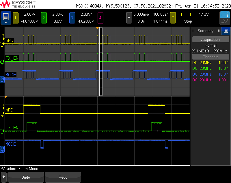
On our custom board the nRF21540 signals are on different nRF5340 pins and therefore I added the following to our board device tree (the nRF21540 SPI signals are not used by the sample code, so I put SPI_CS fix to high and SPI_SCK, SPI_MOSI, SPI_MISO fix to low):

    gpio_fwd: nrf-gpio-forwarder {
        compatible = "nordic,nrf-gpio-forwarder";
        status = "okay";

        nrf21540-gpio-if {
            gpios = <&gpio0 30 0>,  /* tx-en-gpios   TP26 */
                <&gpio1 12 0>,      /* rx-en-gpios   TP20 */
                <&gpio1 10 0>,      /* pdn-gpios     TP19 */
                <&gpio0 31 0>,      /* ant-sel-gpios TP27 */
                <&gpio1 13 0>;      /* mode-gpios    TP21 */
        };
    };

But with this configuration the nRF21540 signals look totally different and there is almost no RF signal (< -80dBm):
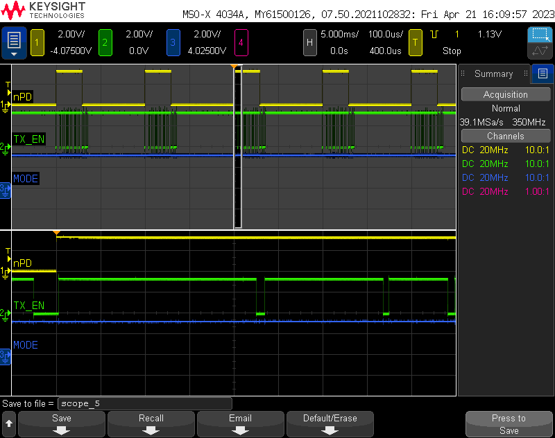
Without nRF21540 our board streams audio correctly.

How do I get our board working with nRF21540?

Regards,
Benno

Parents
  • Hello,

    I don't see anything wrong with the overlay you posted. Can you please try to place a breakpoin at ble_hci_vsc_nrf21540_pins_set() in ble_core.c to verify that it is reached? This is the HCI command to make the controller configure the FEM control pins.

    Thanks,

    Vidar

  • Hi Vidar.

    Yes, ble_hci_vsc_nrf21540_pins_set() gets called.

    The LE audio controller part (ble5-ctr-rpmsg_3330.hex) uses also some additional GPIO for UART and LED. I removed the corresponding nrf-gpio-forwarder sections (uart and leds) in the device tree of our board. But two of these GPIO (P0.30 and P1.10) are used on our board as nRF21540 signals and get therefore forwarded (see device tree snippet above).

    Could this lead to a conflict in the controller?

    Regards,
    Benno

  • Hi Benno,

    I think you are onto something. One of our developers also pointed out that that there was someoverlap in your pin assignments. Are you using SDK v2.3.0 or another version with ble5-ctr-rpmsg_3330.hex?

    Thanks,

    Vidar

    Edit: could you please try to comment the controller_leds_mapping() line at 

  • Hi Vidar.

    I could see a conflict on P0.30 and P1.10. But why is the MODE signal on P1.13 affected also?

    Yes, I use SDK v2.3.0.

    At the moment the code in ble_core.c you mentioned, is already commented out (rgb2_green and rgb2_red do not exist on our board). What if I map PAL_LED_ID_CPU_ACTIVE and PAL_LED_ID_ERROR to unused GPIO, could that change the behavior?

    Anyway, if there is a conflict of GPIO configurations between our board and ble5-ctr-rpmsg_3330.hex, how can we solve that (beside changing our board of course)?

    Regards,
    Benno

  • Hi Benno,

    so I put SPI_CS fix to high and SPI_SCK, SPI_MOSI, SPI_MISO fix to low):

    There might be some conflict here as the MODE pin (P1.13) is the same pin that is being assigned to the SPI MISO by default. Though I am not sure where the conflict could be considering the BT controller is only using the GPIO control interface.

    We tried to reproduce this by applying the patch below, but the control signals were correct in our case. Could you try please try with the same changes on your side?

    diff --git a/applications/nrf5340_audio/prj.conf b/applications/nrf5340_audio/prj.conf
    index 481ac61f3..6eb7a9bd8 100644
    --- a/applications/nrf5340_audio/prj.conf
    +++ b/applications/nrf5340_audio/prj.conf
    @@ -60,3 +60,5 @@ CONFIG_DEVICE_SHELL=n
     CONFIG_SD_LOG_LEVEL_OFF=y
     
     CONFIG_SENSOR=y
    +CONFIG_TRANSPORT_BIS=y
    +CONFIG_AUDIO_SOURCE_I2S=y
    \ No newline at end of file
    diff --git a/applications/nrf5340_audio/src/audio/streamctrl.c b/applications/nrf5340_audio/src/audio/streamctrl.c
    index 5f6f83b89..e18099a8c 100644
    --- a/applications/nrf5340_audio/src/audio/streamctrl.c
    +++ b/applications/nrf5340_audio/src/audio/streamctrl.c
    @@ -375,8 +375,8 @@ static void le_audio_evt_handler(enum le_audio_evt_type event)
     
     		audio_system_start();
     		stream_state_set(STATE_STREAMING);
    -		ret = led_blink(LED_APP_1_BLUE);
    -		ERR_CHK(ret);
    +		//ret = led_blink(LED_APP_1_BLUE);
    +		//ERR_CHK(ret);
     
     		break;
     
    diff --git a/applications/nrf5340_audio/src/bluetooth/ble_core.c b/applications/nrf5340_audio/src/bluetooth/ble_core.c
    index 6537f8d98..1b25abd51 100644
    --- a/applications/nrf5340_audio/src/bluetooth/ble_core.c
    +++ b/applications/nrf5340_audio/src/bluetooth/ble_core.c
    @@ -125,11 +125,11 @@ static void on_bt_ready(int err)
     		DT_PATH(nrf_gpio_forwarder, nrf21540_gpio_if), gpios, 4);
     
     	struct ble_hci_vs_cp_nrf21540_pins nrf21540_pins = {
    -		.mode = mode_pin,
    -		.txen = tx_pin,
    -		.rxen = rx_pin,
    -		.antsel = ant_pin,
    -		.pdn = pdn_pin,
    +		.mode = 45,
    +		.txen = 30,
    +		.rxen = 44,
    +		.antsel = 31,
    +		.pdn = 42,
     		/* Set CS pin to ffff since we are not using the SPI */
     		.csn = 0xffff
     	};
    @@ -155,20 +155,6 @@ static int controller_leds_mapping(void)
     {
     	int ret;
     
    -	ret = ble_hci_vsc_led_pin_map(PAL_LED_ID_CPU_ACTIVE,
    -				      DT_GPIO_FLAGS_BY_IDX(DT_NODELABEL(rgb2_green), gpios, 0),
    -				      DT_GPIO_PIN_BY_IDX(DT_NODELABEL(rgb2_green), gpios, 0));
    -	if (ret) {
    -		return ret;
    -	}
    -
    -	ret = ble_hci_vsc_led_pin_map(PAL_LED_ID_ERROR,
    -				      DT_GPIO_FLAGS_BY_IDX(DT_NODELABEL(rgb2_red), gpios, 0),
    -				      DT_GPIO_PIN_BY_IDX(DT_NODELABEL(rgb2_red), gpios, 0));
    -	if (ret) {
    -		return ret;
    -	}
    -
     	return 0;
     }
     
    diff --git a/applications/nrf5340_audio/src/main.c b/applications/nrf5340_audio/src/main.c
    index 85d2701c2..57abca68d 100644
    --- a/applications/nrf5340_audio/src/main.c
    +++ b/applications/nrf5340_audio/src/main.c
    @@ -166,8 +166,8 @@ void main(void)
     	ret = hfclock_config_and_start();
     	ERR_CHK(ret);
     
    -	ret = led_init();
    -	ERR_CHK(ret);
    +	//ret = led_init();
    +	//ERR_CHK(ret);
     
     	ret = button_handler_init();
     	ERR_CHK(ret);
    @@ -207,8 +207,8 @@ void main(void)
     		(void)k_sleep(K_MSEC(100));
     	}
     
    -	ret = leds_set();
    -	ERR_CHK(ret);
    +	//ret = leds_set();
    +	//ERR_CHK(ret);
     
     	audio_system_init();
     
    diff --git a/applications/nrf5340_audio/tools/buildprog/nrf5340_audio_dk_devices.json b/applications/nrf5340_audio/tools/buildprog/nrf5340_audio_dk_devices.json
    index 0a42fe365..5d1737377 100644
    --- a/applications/nrf5340_audio/tools/buildprog/nrf5340_audio_dk_devices.json
    +++ b/applications/nrf5340_audio/tools/buildprog/nrf5340_audio_dk_devices.json
    @@ -5,7 +5,7 @@
             "channel": "left"
      },
      {
    -        "nrf5340_audio_dk_snr": 1000,
    +        "nrf5340_audio_dk_snr": 1050179200,
             "nrf5340_audio_dk_dev": "gateway",
             "channel": "NA"
      },
    diff --git a/boards/arm/nrf5340_audio_dk_nrf5340/nrf5340_audio_dk_nrf5340_cpuapp_common.dts b/boards/arm/nrf5340_audio_dk_nrf5340/nrf5340_audio_dk_nrf5340_cpuapp_common.dts
    index 991b0ae34..cf6e962f2 100644
    --- a/boards/arm/nrf5340_audio_dk_nrf5340/nrf5340_audio_dk_nrf5340_cpuapp_common.dts
    +++ b/boards/arm/nrf5340_audio_dk_nrf5340/nrf5340_audio_dk_nrf5340_cpuapp_common.dts
    @@ -20,12 +20,6 @@
     	gpio_fwd: nrf-gpio-forwarder {
     		compatible = "nordic,nrf-gpio-forwarder";
     		status = "okay";
    -		uart {
    -			gpios = <&gpio1 9 0>, <&gpio1 8 0>, <&gpio1 11 0>, <&gpio1 10 0>;
    -		};
    -		leds {
    -			gpios = <&gpio0 28 0>, <&gpio0 29 0>, <&gpio0 30 0>;
    -		};
     	};
     
     	arduino_header: connector {
    diff --git a/boards/shields/nrf21540_ek/nrf21540_ek_fwd.overlay b/boards/shields/nrf21540_ek/nrf21540_ek_fwd.overlay
    index 5645b3949..3b8e42236 100644
    --- a/boards/shields/nrf21540_ek/nrf21540_ek_fwd.overlay
    +++ b/boards/shields/nrf21540_ek/nrf21540_ek_fwd.overlay
    @@ -15,11 +15,11 @@
      */
     &gpio_fwd {
     	nrf21540-gpio-if {
    -		gpios = <&arduino_header 11 0>,		/* tx-en-gpios */
    -			<&arduino_header 9 0>,		/* rx-en-gpios */
    -			<&arduino_header 15 0>,		/* pdn-gpios */
    -			<&arduino_header 10 0>,		/* ant-sel-gpios */
    -			<&arduino_header 8 0>;		/* mode-gpios */
    +            gpios = <&gpio0 30 0>,  /* tx-en-gpios   TP26 */
    +                <&gpio1 12 0>,      /* rx-en-gpios   TP20 */
    +                <&gpio1 10 0>,      /* pdn-gpios     TP19 */
    +                <&gpio0 31 0>,      /* ant-sel-gpios TP27 */
    +                <&gpio1 13 0>;      /* mode-gpios    TP21 */
     	};
     	nrf21540-spi-if {
     		gpios = <&arduino_header 16 0>,		/* cs-gpios */
    

    Thanks,

    Vidar

  • Hi Vidar.

    I could not reproduce your results with the patches you provided. I applied the patches to the original LE audio sample code and measured the nRF21540 signals on the nRF5340 Audio DK, but without connecting the shield. I measured the following:

    • PDN signal on P1.10 is fixed low
    • MODE signal on P1.13 has 6 positive 91us pulses every 10ms
    • ANT_SEL signal on pin P0.31 has a 3.84ms positive pulse every 10ms interrupted by 5 negative 15us pulses
    • TX_EN signal on P0.30 I could not measure because it is only routed to RGB2_LED
    • RX_EN signal on P1.12 is fixed low but with strong noise (interference from SPI CS?)

    Because P1.10 could collide with a netcore UART signal I re-mapped the PDN signal to P1.14, and because I could not measure P0.30 I re-mapped the TX_EN signal to P1.00. Now I measured the following:

    • PDN signal on P1.14 has 6 positive 56us pulses every 10ms
    • MODE signal on P1.13 has 6 positive 91us pulses every 10ms
    • ANT_SEL signal on pin P0.31 has a 3.84ms positive pulse every 10ms interrupted by 5 negative 15us pulses
    • TX_EN signal on P1.00 is fixed low
    • RX_EN signal on P1.12 is fixed low but with strong noise

    P1.14 has now exact the waveform of the TX_EN signal of the original LE audio sample, but it is mapped to the ble_hci_vs_cp_nrf21540_pins.pdn field in ble_core.c. Equally P1.13 corresponds to the PDN signal but is mapped to the ble_hci_vs_cp_nrf21540_pins.mode field and P0.31 corresponds to the MODE signal, but is mapped to the ble_hci_vs_cp_nrf21540_pins.antsel field.

    My conclusion:

    • At least P1.10 (but probably P0.30 also) cannot be used as a nRF21540 signal.
    • The vendor specific HCI command HCI_OPCODE_VS_CONFIG_FEM_PIN is differently interpreted on the controller side and therefore the signal mapping gets mangled.

    Can you agree with my conclusions?

    Is it possible to provide us with a controller image, which correctly maps the nRF21540 signals and the netcore UART and LED signals do not interfere with the nRF21540 signals?

    Regards,
    Benno

  • Hi Benno,

    The developer who was trying to reproduce your problem here pointed out that you have to turn off the DEBUG ENABLE switch if measuring on the AUDIO DK:

    To test with the diff, we have to make sure we compile the code with adding --nrf21540 in the end

    $ python buildprog.py -c both -d gateway -b debug -p --pristine --nrf21540

    So the build system will involve the nrf21540_ek_fwd.overlay and forwarding the GPIO control permission to network core.
    Before we measure the signal on nRF5340 audio DK, we have to turn off the "DEBUG ENABLE" switch, otherwise P1.10 will be pull down to low since it is connected to J-Link chip.
    The current controller won't send anything through UART pins, so we still can use those pins for controlling FEM
    And would be great if customer can share the compiled DTS from nrf/applications/nrf5340_audio/build/dev_gateway/build_debug/zephyr/zephyr.dts
    So the DEBUG switch should explain why PDN stayed low in your case. 
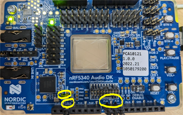
    P0.30 is a bit tricky, it is exposed on TP59 here:
    Are you able to provide the generated device tree file (zephyr.dts) as the developer requested?
    Thanks,
    Vidar
Reply
  • Hi Benno,

    The developer who was trying to reproduce your problem here pointed out that you have to turn off the DEBUG ENABLE switch if measuring on the AUDIO DK:

    To test with the diff, we have to make sure we compile the code with adding --nrf21540 in the end

    $ python buildprog.py -c both -d gateway -b debug -p --pristine --nrf21540

    So the build system will involve the nrf21540_ek_fwd.overlay and forwarding the GPIO control permission to network core.
    Before we measure the signal on nRF5340 audio DK, we have to turn off the "DEBUG ENABLE" switch, otherwise P1.10 will be pull down to low since it is connected to J-Link chip.
    The current controller won't send anything through UART pins, so we still can use those pins for controlling FEM
    And would be great if customer can share the compiled DTS from nrf/applications/nrf5340_audio/build/dev_gateway/build_debug/zephyr/zephyr.dts
    So the DEBUG switch should explain why PDN stayed low in your case. 
    P0.30 is a bit tricky, it is exposed on TP59 here:
    Are you able to provide the generated device tree file (zephyr.dts) as the developer requested?
    Thanks,
    Vidar
Children
Related