nPM1100 - Current consumption is higher than expected

Hi all,

I'm working on a custom design based on nPM1100 and nRF52832. It's a battery powered device that's intended to be on at all time, so I'm taking some care about current consumption.
I've assembled a simplified version of the board with just PMIC, MCU and required passive components.

The chip is running an empty loop with WFE instruction, on a standalone board I'm measuring about 30 uA with that setup and I'm quite happy with it.
However, on my new board I'm measuring about 2200 uA of current, and that's very off.

The only guess I have is VSYS decoupling, which is just missed on this board (since I'm not using VSYS at all). But I'm not sure if that can lead to such issue. It somewhat makes sense - currently there is no battery-side DC-DC decoupling at all and I guess this can lead to improper DC-DC operation.

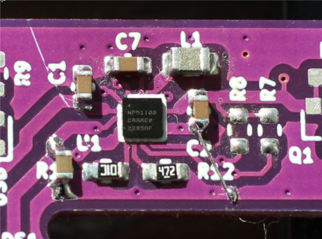
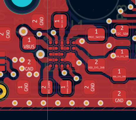
This is the relevant part of the schematics and a part of the PCB with the chip.


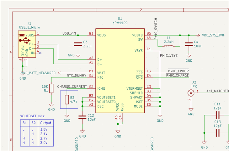
Can you confirm if my initial guess is correct or there is anything else that I can check?
Thanks!

  • Hello,

    I can't think of anything else either. Likely the regulator is not stable here.

    Kenneth

  • Since this board does not allow me to install that capacitor I've temporary switched to another board with slightly inferior layout but easier access to traces. So that's what I have so far:


    All caps are X5R 10uF 6.3V (C1608X5R0J106M080AB). R12 is charge current selection, R1 is NTC stub. L1 is the main coil (DFE201210U)

    The consumption is still around 2200 uA...

    I'm not really sure where to look next. The chip is hand-soldered but I doubt something is shorted. I got pretty stable results with both lead-free and reballed leaded solder (with stable output voltage and working charger and indications)

    There are no other components on this board besides the battery.

  • So from my understanding you have 3 layouts here, 1 that works and 2 the fails (do them fail or is the current just high). Could be interesting to compare them in more details (schematic and layout, possible also any voltages to see if they compare), I assume all designs are using the same revision of the nPM1100 here, what have you done with the pins not shown in your schematic?

    Kenneth

  • I only have 2 designs (the one that I mentioned at the beginning is just a standalone MCU to measure the firmware consumption - to make sure it's not affecting the test). I don't think I have a properly working nPM1100 design at my disposal.
     
    All chips or parts that I have came from either Mouser or Digikey. All nPM1100 and inductors are from the same order (so I assume from the same batch)

    Both of the designs use the same schematic component and library (so there may be issues, even though I'm not seeing em)

    There doesn't seem to be other failures besides high current consumption. Charging and indications seem to work just fine.

    One thing that maybe raises my brow is that reference layout has D3 and D4 pins (ship mode) disconnected (or maybe connected to inner layers?) In my design they are shorted to common ground.

    Kicad symbols have a tendency to hide pins that have the same purpose (so that's why you don't see B2 pin, for example - however it's correctly connected on the board)

    Overall the design is so simple I can't see any potential pitfalls here. Weird.


Related