[nRF24L01+] How to use Auto Acknowledge

Hello all,

1. I have a transmitter (Arduino Pro Mini 5V) connected to a nRF24L01+. I use the following code to set up the radio.

    radio.begin();
    radio.setChannel(125);
    radio.setPALevel(RF24_PA_LOW);
    radio.setDataRate(RF24_1MBPS);
    radio.setAddressWidth(5);
    radio.setAutoAck(true);
    radio.setRetries(5, 3);
    radio.setPayloadSize(sizeof(radio_data));
    radio.openWritingPipe(address);
    radio.stopListening();

2. I have a receiver (ESP32) coonecter to a nRF24L01+. I use the following code to set up the radio.

    radio.begin();
    radio.setChannel(125);
    radio.setPALevel(RF24_PA_LOW);
    radio.setDataRate(RF24_1MBPS);
    radio.setAddressWidth(5);
    radio.setAutoAck(true);
    radio.setRetries(5, 3);
    radio.setPayloadSize(sizeof(radio_data));
    radio.openReadingPipe(0, address);
    radio.startListening();

3. When I want to transmit data, I call the function write.

The return of the call to the function write is always false, meaning that auto acknowledgement goes wrong.

Have you any idea of what I did wrong ?

Thanks for your help.

Parents
  • Hi 

    Is anything received by the ESP32 board?

    The nRF24L01+ is rated to 3.6V maximum, so I think the first order of business would be to test this on boards that support a lower supply voltage. Correct behavior can not be guaranteed when you're running the nRF device at 5V, and it might damage the module over time. 

    Best regards
    Torbjørn

  • Hello,

    First, the nRF24L01+ is not supplied with the 5V of transmitter Arduino, but with 3.3V.

    Second, with the channel set to 125, the receiver ESP32 is not receiving at all. If I remove the call to setChannel, the ESP32 is receiving around 20% of the frame and in that case, the Arduino is getting the ACK.
    So, 80% of frame are lost with no ACK.

    As an information, there is a 10µF capacitor at the pin GND/3.3V of the receiver nRF24L01+ and a 100µF capacitor for the transmitter nRF24L01+.

    Best regards.

  • Hi 

    _pascalh said:
    First, the nRF24L01+ is not supplied with the 5V of transmitter Arduino, but with 3.3V.

    Ok, but have you made sure that the Arduino can properly read the logic signals coming back from the nRF24L01+, which will run at 3.3V? I assume the SPI bus from the Arduino is running at 5V. 

    Do you have a picture of the modules you are using? 
    Where did you get them? 

    There are a lot of fake nRF234L01+ modules around, which may or may not work as well as the genuine parts. If we suspect that you are having fake parts I recommend ordering a couple of modules from a reputable vendor to see if you get the same issues or not. 

    Best regards
    Torbjørn

  • Hello,

    Even if you're right that my part is not genuine, it seems to work correctly.

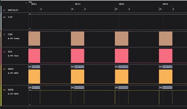
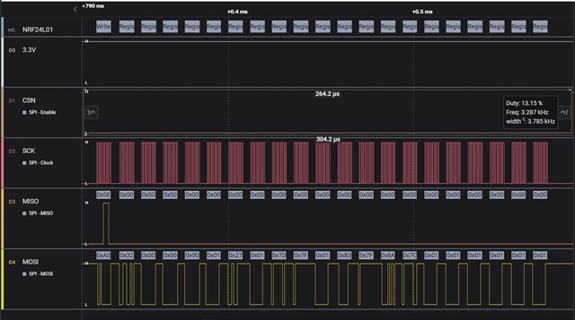
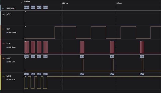
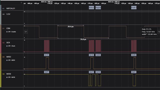
    Here after are some evidences. I use a digital oscilloscope to get them. It also to decode the nRF24 protocol (see information squared in grey).

    1. Frames exchanged every 100ms between Arduino transmitter and nRF24.

    2. At the begining of each frame, there is a TX payload.

    3. After the TX payload, it seems to wait for the ACK from the receiver.

    4. At the end of the frame, finally with no ACK, the trnasmitter decides to stop.

    Best regards.

Reply
  • Hello,

    Even if you're right that my part is not genuine, it seems to work correctly.

    Here after are some evidences. I use a digital oscilloscope to get them. It also to decode the nRF24 protocol (see information squared in grey).

    1. Frames exchanged every 100ms between Arduino transmitter and nRF24.

    2. At the begining of each frame, there is a TX payload.

    3. After the TX payload, it seems to wait for the ACK from the receiver.

    4. At the end of the frame, finally with no ACK, the trnasmitter decides to stop.

    Best regards.

Children
Related