Supply a high-speed clock signal from NORA-B106-00B (nRF5340) to an external ADC

Hi,

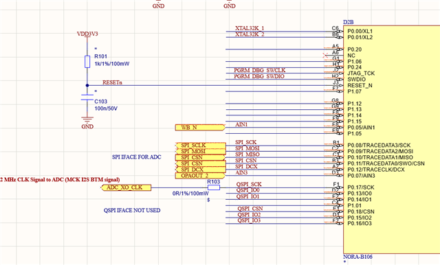
I need to provide a clock signal of 4.9152 MHz to an external ADC.

Can the NORA-B106 module (that integrate a nRF5340) supply that signal by the Application Core M33?

References?


Many Thanks for your support

Parents
  • Hello,

    I have not done any calculations on this myself, but I guess the closest you could get would be to use the Audio PLL of the I2S peripheral: https://infocenter.nordicsemi.com/topic/ps_nrf5340/i2s.html#concept_ezd_bqy_vr 

    Though you will be "wasting" a few pins by using the I2S peripheral, since the I2S peripheral will use some pins for the other I2S pins at the same time, and you will to setup and configure the I2S peripheral even if you are indirectly only want the MCK.

    Kenneth

  • Hi,

    The idea to generate the 4.9152MHz clock by using the MCLK of a I2S interface is a good idea... but...

    Actually the pins (P0.08, P0.09, P0.10, P0.11 & P0.12 of the NORA-B106 are filled by with a SPI interface (the schematic is in design phase therefore it's not mandatory to keep the design fixed) to an ADC. If I don't remember bad, the SPI, the I2C, the UART, The PDM, the NFC, the PWM and so on... shares the pins with the I2S interface .

    Also we have a QSPI iface free ... maybe I can substitute the SPI with the QSPI to connect toghether the BLE Module and the ADC and configure the (now) free SPI  as I2S to implement your suggested solution?

    Looking the UBLOX NORA DS (UBX-20027119 - R10 C1 Public, pag 17/46 & CHAPTER 3 PAG 22/46) I was not able to find the I2S's pin location? Where are them defined? where I can fint the doc to understand exactly how to connect the module to the other circuitries?

    Many thanks for your support,
    Have a nice day & Best Regards

Reply
  • Hi,

    The idea to generate the 4.9152MHz clock by using the MCLK of a I2S interface is a good idea... but...

    Actually the pins (P0.08, P0.09, P0.10, P0.11 & P0.12 of the NORA-B106 are filled by with a SPI interface (the schematic is in design phase therefore it's not mandatory to keep the design fixed) to an ADC. If I don't remember bad, the SPI, the I2C, the UART, The PDM, the NFC, the PWM and so on... shares the pins with the I2S interface .

    Also we have a QSPI iface free ... maybe I can substitute the SPI with the QSPI to connect toghether the BLE Module and the ADC and configure the (now) free SPI  as I2S to implement your suggested solution?

    Looking the UBLOX NORA DS (UBX-20027119 - R10 C1 Public, pag 17/46 & CHAPTER 3 PAG 22/46) I was not able to find the I2S's pin location? Where are them defined? where I can fint the doc to understand exactly how to connect the module to the other circuitries?

    Many thanks for your support,
    Have a nice day & Best Regards

Children
Related