Interfacing LSM6DS3TR-C with SPI NRF9160

Hi,

I am using the nrf9160dk board to interface the IMU Sensor LSM6DS3TR-C using SPI. 

I'm trying to run through the LSM6DSL sensor interface, I've read the documentation for both sensors and they use the same register addresses, so I don't believe that should be the problem....

I've read several very similar questions here on the devzone, but none of them helped me...

I'm running the example of the zephyr sdk itself (https://github.com/zephyrproject-rtos/zephyr/tree/main/samples/sensor/lsm6dsl) but without success so far.

I made the following changes:

My devicetree overlay:

/ {
	aliases {
		lsm6dsl1 = &lsm6dsl1;
	};
};

&pinctrl {
    spi1_default: spi1_default {
		group1 {
			psels = < NRF_PSEL(SPIM_SCK, 0, 11) >,
					<NRF_PSEL(SPIM_MOSI, 0, 9)>,
					<NRF_PSEL(SPIM_MISO, 0, 8)>;
		};
	};

	spi1_sleep: spi1_sleep {
		group1 {
			psels = <NRF_PSEL(SPIM_SCK, 0, 11)>,
					<NRF_PSEL(SPIM_MOSI, 0, 9)>,
					<NRF_PSEL(SPIM_MISO, 0, 8)>;
			low-power-enable;
		};
	};
};

&spi1 {
    compatible = "nordic,nrf-spim";
    status = "okay";
    pinctrl-0 = <&spi1_default>;
    pinctrl-1 = <&spi1_sleep>;
    pinctrl-names = "default", "sleep";
	cs-gpios = < &gpio0 10 GPIO_ACTIVE_LOW >;
    lsm6dsl1: lsm6dsl@0 {
		compatible = "st,lsm6dsl";
		status = "okay";
		reg = <0x0>;
		// spi 10MHz
		spi-max-frequency = <10000000>;
	};
};

&spi3 {
	status = "disabled";
};

In the prj.conf file I didn't make any changes, and in my main.c I just made the following change, to get the device information and check if it's not null...

const struct device *const lsm6dsl_dev = DEVICE_DT_GET(DT_NODELABEL(lsm6dsl1));

printk("LSM6DSL test app\n");

if (lsm6dsl_dev == NULL) {
	printk("Could not get LSM6DSL device\n");
	return 0;
}

if (!device_is_ready(lsm6dsl_dev)) {
	printk("sensor: device not ready.\n");
	return 0;
}

But when running the code the output has been the same:
*** Booting Zephyr OS build v3.2.99-ncs2 ***
LSM6DSL test app
sensor: device not ready.

Can you help me with an error that I'm not seeing?

Thanks

Parents
  • Hi,


    P0.11 goes to the external memory on the nRF9160-DK.

    P0.08/P0.09 goes to the switches, so depending on their position, those GPIOs can potentially be grounded

    See here for more information: https://infocenter.nordicsemi.com/topic/ug_nrf91_dk/UG/nrf91_DK/if_connector.html?cp=2_0_4_3_5


    I would recommend that you probe these pins to see if they behave as expected.


    Kind regards,

    Håkon

  • Hi Håkon,

    Thanks for the feedback, unfortunately it's still not working...

    I checked the pins as you recommended and indeed one of them was grounded, but I tried switching to other gpios and still didn't get any results...

    / {
    	aliases {
    		lsm6dsl1 = &lsm6dsl1;
    	};
    };
    
    &pinctrl {
        spi1_default: spi1_default {
    		group1 {
    			psels = < NRF_PSEL(SPIM_SCK, 0, 19) >,
    					<NRF_PSEL(SPIM_MOSI, 0, 18)>,
    					<NRF_PSEL(SPIM_MISO, 0, 21)>;
    		};
    	};
    
    	spi1_sleep: spi1_sleep {
    		group1 {
    			psels = <NRF_PSEL(SPIM_SCK, 0, 19)>,
    					<NRF_PSEL(SPIM_MOSI, 0, 18)>,
    					<NRF_PSEL(SPIM_MISO, 0, 21)>;
    			low-power-enable;
    		};
    	};
    };
    
    &spi1 {
        compatible = "nordic,nrf-spim";
        status = "okay";
        pinctrl-0 = <&spi1_default>;
        pinctrl-1 = <&spi1_sleep>;
        pinctrl-names = "default", "sleep";
    	cs-gpios = < &gpio0 17 GPIO_ACTIVE_LOW >;
        lsm6dsl1: lsm6dsl@0 {
    		compatible = "st,lsm6dsl";
    		status = "okay";
    		reg = <0x0>;
    		spi-max-frequency = <10000000>;
    		irq-gpios = < &gpio0 22 GPIO_ACTIVE_LOW >;
    	};
    };
    
    &spi3 {
    	status = "disabled";
    };

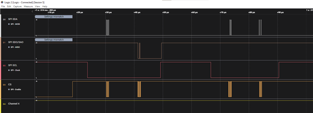
    I'm trying to get the signals on the oscilloscope to see if the behavior of the spi is visible, but still nothing.

    I tested the sensor on an arduino and it worked normally, so it's something I'm missing on the nRf9160.

    Any more suggestions?

  • Hi,


    The pins you're using now overlaps with the pins that are directly connected to the nRF52840 on the nRF9160-DK. Depending on the configuration of the board controller, these GPIOs could be directly connected from nRF9160->nRF52840.

    Mindtech said:
    I checked the pins as you recommended and indeed one of them was grounded,

    If you set the switch 1 and switch 2 in the "NC" position, they should not interfere with the signal on P0.08/P0.09.


    I would recommend that you use a logic analyzer to see which GPIOs are toggling.


    Kind regards,

    Håkon

Reply
  • Hi,


    The pins you're using now overlaps with the pins that are directly connected to the nRF52840 on the nRF9160-DK. Depending on the configuration of the board controller, these GPIOs could be directly connected from nRF9160->nRF52840.

    Mindtech said:
    I checked the pins as you recommended and indeed one of them was grounded,

    If you set the switch 1 and switch 2 in the "NC" position, they should not interfere with the signal on P0.08/P0.09.


    I would recommend that you use a logic analyzer to see which GPIOs are toggling.


    Kind regards,

    Håkon

Children
Related