###Other relevant posts
- For an overview of current measurement basics, see this post: Introduction
- For a concise guide to setting up measurement equipment with the nRF52832 development kit, see this post: Measuring current with PCA10040 v0.9.0
###Outline
- Errata affecting the current measurements
- DCDC does not automatically switch off in System ON IDLE
- NFCT can draw current when not enabled
- Measurements
- Results
- Test setup: Power analyzer
- Power Analyzer Measurements
- Test setup: Oscilloscope and ampere-meter
- Oscilloscope Measurements
Errata affecting the current measurements
###DCDC does not automatically switch off in System ON IDLE Please read this erratum for more information: [63]
The DCDC draws a base current while active. When the device load current is very low, this base current will be higher than the current saved by efficient buck regulation. The DCDC converter is therefore switched off by the hardware power management system when the load current is low. The Errata means the DCDC is not switched off when it should be, and its base current will impact the measurement of current when the device goes to low power modes.
In application code, you have the option to either turn on or off the DCDC. If the DCDC is on all the time for the Engineering B revision of the nrF52832, you will get the correct current consumption during radio and CPU activity, but too high consumption during low power modes. If you turn off the DCDC, you will see higher than expected average current for BLE events because the Radio and CPU peak currents are higher without the DCDC converter.
To overcome this issue some modifications to the application code need to be implemented to manually control the DCDC to be on when the Radio is on, and off when in low power modes.
Note: The DCDC is not on all the time the CPU is running. This will mean the CPU run current is higher than expected for the SoftDevice and the application. If the application executes code when measuring current, the CPU current will be higher than expected.
Instead of the regular sd_app_evt_wait() function called in the main loop in main.c, we can write a custom code that waits for an event, and then turns the DCDC on or off based on the radio state (on or off).
Replace the main for loop with this code:
for (;;)
{
    do{
        __WFE();
    }while (!NRF_RADIO->POWER);
    NRF_POWER->DCDCEN = 1;
    NRF_TIMER0->TASKS_START = 1;
    NRF_TIMER0->TASKS_STOP = 1;
    do{
       __WFE();
    }while (NRF_RADIO->POWER);
    NRF_TIMER0->TASKS_SHUTDOWN = 1;
    NRF_POWER->DCDCEN = 0;
    (void)sd_power_mode_set((nrf_power_mode_t) 1);
}
This code is only useful for doing current measurements and should not be used when developing an application.
###NFCT can draw current when not enabled Another relevant Errata is regarding the NFCT peripheral which can cause increased current consumption in System OFF and System ON IDLE. Please see this erratum for more information: [62]
The problem does not occur until the supply voltage (VDD) is higher than 2.5V, but you should be aware of this issue in case you see increased consumption during low power modes.
##Measurements This section will show current consumption measured by Nordic using nRF52832 Engineering B on the PCA10040 kit with S132 v2.0.0-7.alpha and using the example application code for measurements in different use cases. These use cases include advertising and connection with different intervals, 100 ms and 1000 ms. It will also show the current draw of a complete adv/con event, the current in System ON IDLE + RTC between BLE events and in System OFF mode. Measurements have been taken using a power analyzer as a reference and to show current profile plots, an ampere meter and an oscilloscope. The results and the setup for each instrument are included.
###Results The results show good correlation between the measurement methods. The Ampere meter does not have results for BLE events further than 100ms apart and the Oscilloscope does not have results for very low current measurements. This is explained in the following parts.
These results are measured using a 2V supply voltage due to Errata 62 affecting current consumption when the supply voltage is high. Normal operating conditions for measurement is 3V supply which would result in between lower average current measurements because the DCDC is more efficient at higher supply voltages. The table contains power analyzer measurements taken with 3V supply on a prototype circuit that resolves Errata 62. The prototype circuit is not available on development kits so you may experience higher averages on the development kit with 3V supply.
| Interval (ms) |
Data (bytes) |
Power analyzer (uA) Vdd=2V |
Power analyzer (uA) Vdd=3V |
Ampere- meter (uA) Vdd=2V |
Oscilloscope (uA) Vdd=2V |
|
| Advertiser | 1000 | 6 | 14.3 | 11.4 | - | 14.3 |
| Advertiser | 100 | 6 | 120 | 94.6 | 120 | 118 |
| Connection | 1000 | 20 | 9.47 | 9.31 | - | 9.3 |
| Connection | 100 | 20 | 80.0 | 65.9 | 80 | 78.1 |
| Sys ON IDLE | - | - | 1.75 | 1.72 | 2 | - |
| Sys OFF | - | - | 0.225 | 0.224 | 0.2 | - |
###Test setup: Power analyzer
- Chip: nRF52832 QFAABA
- Softdevice: s132_nrf52_2.0.0-7.alpha
- Application: modified app_pwr_profiling example from nRF52_SDK_0.9.2
- Equipment: Keysight N6705B Power Analyzer with N6781A module
- External supply Voltage: 2 V
- Data Log Range, Current: Auto
- Sampling frequency: 195312 samples / sec
- TX power: 0 dBm
Advertising mode is using directed advertisement packets to get rid of scan requests, in order to get consistent measurements. This means that the payload of the packets is fixed at 6 bytes.
Connection mode is using notifications to send 20 bytes of data in one packet.
###Power Analyzer Measurements In all plots, the larger peaks are BLE events (advertising or connection) and the smaller peaks in between are the low power regulator drawing current periodically in refresh mode.
**Advertising 1000ms **
Avg: 14.3 uA.
Advertising 100ms
Avg: 120 uA
Connection 1000ms
Avg: 9.47 uA
Connection 100ms
Avg: 80.0 uA
System ON IDLE
Measured in between advertising events
Avg: 1.75 uA
System OFF
Avg: 0.255 uA
###Test setup: Oscilloscope and ampere-meter
- Chip: nRF52832 QFAABA
- Softdevice: s132_nrf52_2.0.0-7.alpha
- Application: modified app_pwr_profiling example from nRF52_SDK_0.9.2
- Equipment: Agilent Infinium 54815A
- External supply voltage: 2V
- Voltage offset: 2V
- Sensitivity: 20mA/div
- Memory depth: 32768 pts
- Sampling rate: 250 kSa/s
- Probes: 1X attenuation
- Other: 9-bit bandwidth limit
- TX power: 0 dBm
It is difficult to get accurate results when measuring low average currents (< 100 uA) using an oscilloscope because the sensitivity is not high enough. The low current periods between BLE events are not accurately measured. The best choice is using an ampere meter together with an oscilloscope.
You can use an ampere meter to measure the average current during System ON IDLE + RTC and System OFF as well as advertising/connection events when the interval is not too long. We have successfully been able to measure the current with an ampere meter during advertising or connection with intervals as long as 100 ms. Intervals above 100 ms are not easy to read because the display will jump between the low and high currents.
You can use an oscilloscope to capture BLE events as well as measuring average current higher then around 100 uA.
###Oscilloscope Measurements
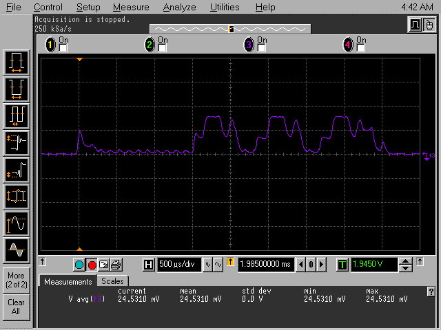
Advertising event
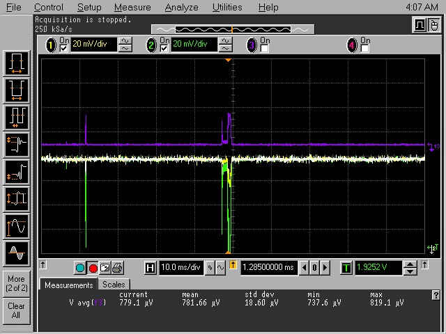
Connection event

Calculating average current from Oscilloscope and Ampere meter measurements
These plots show that the average current consumption during an advertising event is,
24.8 mV / 10 Ohm = 2.48 mA
The captured event lasts for,
500 us/div * 10 divs = 5ms
We then calculate the average current consumption during 1000ms adverting intervals:
5ms/1000ms * 2.45 mA = 12,25 uA
If we add the System ON IDLE + RTC current measured by the ampere-meter, we get:
12,25 uA + 2,0 uA = 14,25 uA
Similarly, for 1000 ms connection interval:
5ms/1000ms * 1.45 = 7.25 uA
7.25 uA + 2,0 uA = 9.25 uA
For higher average current we can use the average values measured on the oscilloscope.
Advertising 100 ms
Avg: 1.18 mV / 10 Ohm = 118 uA
Connection 100 ms
Avg: 781 uV / 10 Ohm = 78.1 uA