

→ Check out the preceding part of this tutorial series before starting on this: nRF Connect SDK Tutorial - Part 1
Welcome to the second part of this tutorial series. Now you know, to a small extent, how samples are built using NCS, and some considerations to take for your particular board. This part will extend on that and go a little deeper. Initially, some vital concepts in NCS will be explained. These concepts are important to understand in general before embarking on your journey with NCS/Zephyr, and also before starting on the practical part of this tutorial. In section 2, I will go through some important aspects regarding setting up a project, and in section 3 I will show how to build more comprehensive applications, where your recently learned knowledge will come in handy.
It is recommended to follow this tutorial series chronologically, but it's not a requirement. Before starting on this part you should at least have done the following:
- Read and executed the instructions in Part 0 of this tutorial series.
- Gone through the first section (Your first "Hello World") of part 1 of this tutorial series
This will help you with setting up the nRF Connect SDK and give you a basic understanding of how to set up a simple example in NCS.
As mentioned in Part 0, you should choose a board and set <board> and <board_variant> accordingly. This applies to this part as well, and when you see one of these variables use your chosen value instead.
Contents
- 1. Concepts in NCS
- 2. Set up a project
- 3 Create a light intensity controller
1. Concepts in NCS
This section has not been updated in a while and some of the information given here might be outdated.
1.1 About NCS
The nRF Connect SDK (NCS) is hosted by Nordic Semiconductor and contains a set of open source projects that makes it possible to develop an application for nRF9160 Cellular IoT devices. NCS consists of several repositories (repos), including the nrf repo, the nrfxlib repo, the MCUboot repo, and the Zephyr Project.
The figure below visualizes the toolchain in NCS, which is based on the Zephyr toolchain. You can see a set of different tools, each playing a role in the creation of an application, from configuring the system to building it.
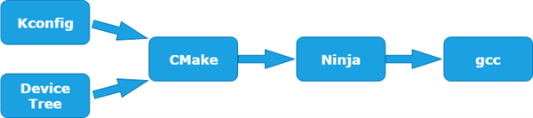
Kconfig generates definitions that configure the whole system, while the Device Tree describes the hardware. Cmake then uses the information from Kconfig and the device tree to generate build files, which Ninja (comparable to make) will use to build the program. The GCC compiler system is used to create the executables. The upcoming chapters will take a closer look at some of these tools.
1.2 West
This section requires the reader to have a basic understanding of how git works.
The Zephyr project includes a tool called west, which makes it possible to manage multiple repositories. This tool is quite useful if your application uses libraries and features from folders that are cloned from different repositories/projects since it keeps control of what commit to use from the different projects. It also makes it fairly simple to add and remove modules. Take a look at the image below, which gives you a good intuition of how it works.
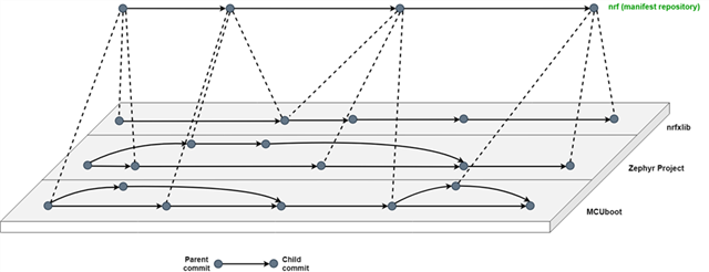
The image shows the content of a west installation, which contains one manifest repository and multiple projects, where the manifest repository controls what commit to use from the different projects. The two most important commands in west are west init and west update, where the former will initialize a new west installation and the latter will update the projects depending on the information in the manifest repository. Take a look at the Zephyr documentation for a more in-depth understanding.
Let's take a closer look at the ncs folder, to get a better perspective of how west works. If you have followed the "nRF Connect Getting Started Guide" correctly the west installation should look as followed:
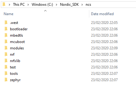
The file .west/config determines the manifest repo and the Zephyr base of the west installation, and as seen in the code snippet below it is set to respectively the nrf folder and the Zephyr folder. This implies that the nrf folder determines what commits to check out for the different projects when running west update. The Zephyr base is a variable that will be used to refer to the Zephyr folder when an application is built.
[manifest]
path = nrf
[zephyr]
base = zephyr
If you open the west manifest (the nrf folder), you will see that it contains a west.yml file. This file contains the revision (tag, branch or SHA) for all the project that is associated with the current nrf revision, and you can see that the projects correspond to the folders in the image above. The west.yml file shows the URL of where the projects are cloned from. E.g. the projects zephyr, mcuboot and nrfxlib are cloned from Nordic Playground on Github. These projects are maintained by Nordic Semiconductor, and you can read more about them in the NCS documentation. Revisit the image at the top of this section, to better visualize how it works.
It is possible to add your own commands to west in addition to the ones managing the multiple git repositories, and the approach is explained in the Zephyr documentation. If you look at the file <sourcecode_root>ncs\zephyr\scripts\west-commands.yml, you can see the extension commands added to west by Zephyr. Later in this tutorial, it will be shown how to build and flash an application using these commands.
1.3 Master vs. Tag
The nrf folder contains west.yml, which turns it into the powerful repository that controls the content of the whole NCS. This makes updates to NCS fairly simple, since all you have to do is to fetch/pull a reliable version of the nrf repository before updating the rest of the projects through west.
You have two choices when developing with NCS. You can work with master or a particular tag. If you choose master, you will use the newest version of the nrf repository, and consequently an up to date ncs folder. The tags represent versions of master at a particular moment in time, and is considered reliable. There is not a correct answer of what to choose, as it depends on your particular need. If reliability is important, and you can't afford unexpected behavior and bugs, then it is recommended to use the latest tag. If it is more important that your project has the newest features than having a reliable solution, then master is the choice to go for.
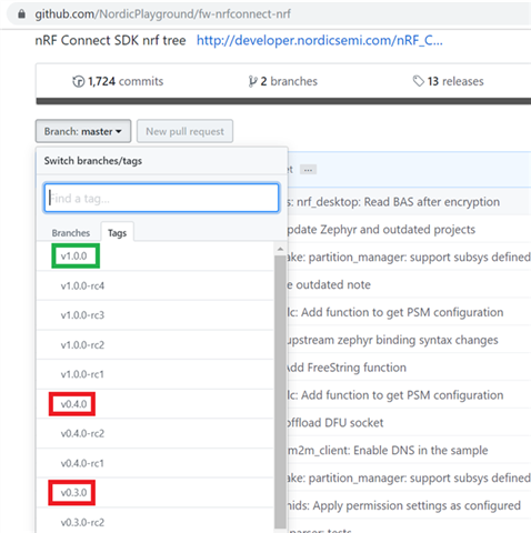
Take a look at the nRF repository, where you find master and all the tags. The image below shows the available tags of this repository at the time this tutorial was written. The tags are enclosed by red and green rectangles, where the green color represents the latest tag, which is most up to date (now v1.2.0).
1.4 The Device Tree
The device tree describes the hardware of a board, everything from the gpio configurations of the LED’s on the nRF9160 DK to the memory location of the ADC peripheral. Device trees give the developer more flexibility and make it easier to modify the hardware. The device tree uses a particular format consisting of nodes connected together, where each node contains a set of properties. Read more about the Device Tree format in the Device Tree Specification. The Zephyr documentation gives a more in-depth explanation of the Device Tree in the context of Zephyr.
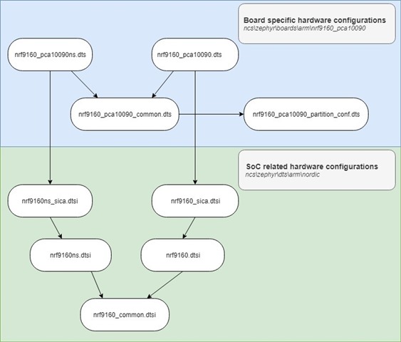
The image below gives an overview of how the different nRF9160 dts/dtsi files include each other. The file that the arrow is pointing away from, includes the file that the arrow is pointing towards. You can see that the dts/dtsi files are organized in a hierarchical manner, where the top files (in the blue area) describes the higher-level hardware like the UART baud rate, I2C SDA and SCL pins and GPIO configuration of LEDs and buttons. The bottom files (in the green area) describe lower-level hardware, like the peripheral's interrupt priority and memory location, base address of SRAM and CPU related information.
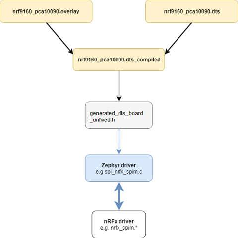
The image below shows what happens with the device tree when building an nRF9160 application. The DTS file is first compiled into a compiled DTS file (nrf9160_pca10090.dts_compiled), where all the defines and macros are resolved before a python script transforms the hardware information into a header file (generated_dts_board_unifixed.h). Both nrf9160_pca10090.dts_compiled and generated_dts_board.h are added to the project's build folder. The drivers will then use this information. The .overlay file is used to modify the device tree. It comes in handy when your project uses external devices, such as a sensor using SPI. Read more about overlay files in the Zephyr documentation.
Let’s go through a specific example, in order to get a better intuition of how this works. Inside <sourcecode_root>\ncs\zephyr\dts\arm\nordic\nrf9160_common.dtsi, there is a node describing the ADC peripheral, and the image below shows how this node is transformed into a set of defines in the header file generated_dts_board_unifixed.h.
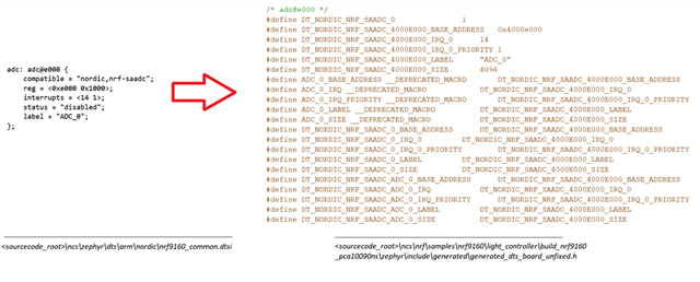
The defines may then be used by drivers or other parts of the compiled code. E.g. DT_NORDIC_NRF_SAADC_ADC_0_BASE_ADDRESS is used by the file nrfx_config_nrf9160.h, which will map the base address of the SAADC peripheral such that it is accessible by the nrfx drivers. See the code snippet below.
#ifdef DT_NORDIC_NRF_SAADC_ADC_0_BASE_ADDRESS
#define NRF_SAADC \
        ((NRF_SAADC_Type *)DT_NORDIC_NRF_SAADC_ADC_0_BASE_ADDRESS)
#endif
1.5 Configurations
In Zephyr, Kconfig files are used to configure the whole system. Specifically, the files give a description of what hardware should be used and how it should be used. The configuration files determine what drivers should be used to interface with the hardware, and also makes it possible to pick and choose specific kind of libraries, software, and other features. The configuration system makes it possible to choose Nordic specific drivers to control peripherals, enable logging and build additional samples such as the Secure Partition Manager sample. There are different kinds of configuration files, including Kconfig and prj.conf files. Read more about them in the Zephyr documentation in Application Configuration and Setting Configuration Values.
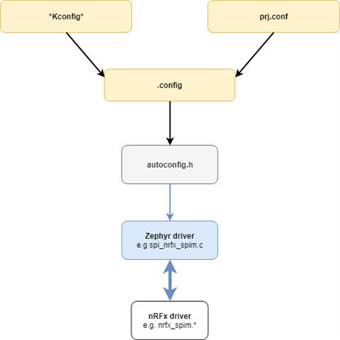
The illustration seen below shows what happens to the systems configurations when an application builds. All the configurations from the Kconfig and the prj.conf files are merged together into a .config file before being transformed into a header file which the nordic specific .c drivers can use.
Let’s go through a specific example to get a deeper understanding of how this process works. Take a look at the configuration I2C_2_NRF_TWIM inside <sourcecode_root>/ncs/zephyr/drivers/i2c/Kconfig.nrfx. Whether it is enabled or not depends on other configurations, such as HAS_HW_NRF_TWIM0, I2C_NRFX and CONFIG_SOC_FAMILY_NRF. The image below shows the transformation of the configuration from Kconfig format to a #define in a header file. Be aware that the build folder may not be present for you since it is first made when a project is built.
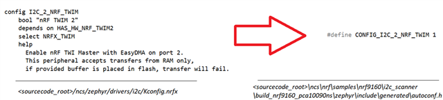
The autoconf.h file is then included into the project and the code snippet below shows how the define is used by the nordic specific Zephyr driver i2c_nrfx_twim.c.
#ifdef CONFIG_I2C_2_NRF_TWIM
    I2C_NRFX_TWIM_DEVICE(2);
#endif
1.6 Secure vs. nonsecure
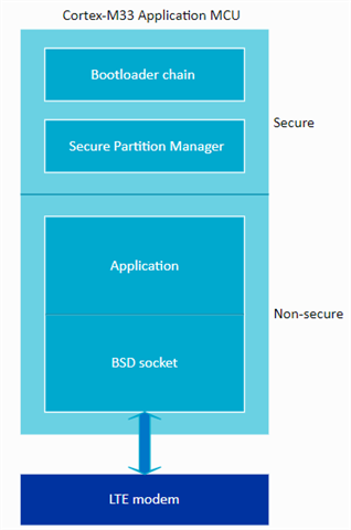
This section is chip-specific, and applies if you are using the nRF5340 DK or the nRF9160 DK. This is because the nRF5340 SoC and the nRF9160 SiP comes with the Arm Cortex-M33 processor and supports secure and non-secure applications. However, this feature is more critical when building applications for the nRF9160, since cellular IoT applications has to be build as non-secure in order to communicate with the modem.
The new TrustZone technology that comes with the Arm Cortex-M33 processor makes it possible to create two environments that can run simultaneously using the same CPU; a secure environment and a non-secure environment. This makes the application more protected from attackers, with the drawback of increased complexity. This section will try to give you a better understanding of this new feature, and how it affects the development process.
A firmware image can be built as Secure or Non-Secure. If a firmware image is built as Secure it will run in the Secure domain and has access to resources (peripherals, memory areas etc..) configured as Secure. Conversely, a Non-Secure firmware can only access Non-Secure resources.
The System protection unit (SPU) peripheral in nRF9160 makes it possible to manage the CPU access to peripherals and memory regions. It does so by configuring the permissions of specific RAM and flash regions and setting the security attributes of peripherals. If a RAM or Flash region’s permission is set as secure, only Secure firmware has access. If a peripheral is configured as Non-Secure, it is mapped to the Non-Secure peripheral address space (0x4xxx_xxxx), and a Secure configuration maps the peripheral to the Secure address space (0x5xxx_xxxx). At reset, all the peripherals are set to Secure.
In order to run a non-secure application, one has to use the SPU to configure the resources as Non-Secure. Luckily, there is already a library with functions that simplifies this process, the Secure Partition Manager (SPM) library. The library is located in <sourcecode_root>/ncs/nrf/subsys/spm. Its API consists of two functions: spm_config() and spm_jump().The function spm_config() will set the security attribute of the peripherals depending on the default configurations in its associated Kconfig file. It will set the flash regions after the SPM location, as Non-Secure, while the RAM regions after the first 64 kB are set as Non-Secure. The function spm_jump() will make the application jump to a Non-Secure partition (e.g. the non-secure user application). The Secure Partition Manager sample uses this library and runs the mentioned functions. Its location is <sourcecode_root>ncs/nrf/samples/nrf9160/spm. By building and flashing this sample in addition to the main application, the main application will run in the non-secure domain.
The image below shows an example of how to use secure/nonsecure environments with the nRF9160
2. Set up a project
If you've followed this tutorial up to this point, you should have a basic idea of how NCS works and how to create a simple project with it. Maybe you are eager to start on your own project? In that case, you should go through this section, as it will provide you with some tips on how to go about this. In the first section, I will show you how to update your application to another tag/master and present one possible workflow for your project. In the last section, I'll demonstrate how to include source and header files to your application, as well as how to modify child images (such as SPM or MCUboot) from the main project
2.1 Manage your project with west
If you are using SES to develop your project, skip this section and go straight to 2.2 Include files and modify child samples/images. If you have installed NCS through the Toolchain Manager, you may go to section 2.2 as well, as this part is not tested yet with the TM. It's only tested with the manual installation of NCS.
2.1.1 How to update NCS to another tag/master
- First, open the command line in <..>\ncs\nrf and run
git checkout v1.3.0 - If you run
git statusyou can see that you are in the tag v1.3.0
C:\Nordic_SDK\ncs\nrf>git status
HEAD detached at v1.3.0
nothing to commit, working tree clean
- Then, open the command line anywhere inside the nrf folder and checkout the master by running
git checkout master
C:\Nordic_SDK\ncs\nrf>git checkout master
Updating files: 100% (1108/1108), done.
Previous HEAD position was 4c0d3be2 west.yml: Update manifest file with v1.3.0 tags
Switched to branch 'master'
Your branch is up to date with 'ncs/master'.
- By running git status again, you can see that you are now in the master
C:\Nordic_SDK\ncs\nrf>git status
On branch master
Your branch is up to date with 'origin/master'.

nothing to commit, working tree clean
- When changing tag/master, the west.yml file may change, in order to update the NCS accordingly, type in the command
west update.
C:\Nordic_SDK\ncs\nrf>west update
=== updating zephyr (zephyr):
Previous HEAD position was b160c8c5ca [nrf fromtree] drivers: flash: nrf_qspi_nor: supports non-aligned read
HEAD is now at 53bfa7b025 [nrf noup] flash_img: mcuboot: reduce NCS patch
M       samples/basic/blinky/src/main.c
M       samples/hello_world/prj.conf
=== updating mcuboot (bootloader/mcuboot):
HEAD is now at 92992c0 [nrf toup] boot: zephyr: Fix build issue for multiple conf files
=== updating mcumgr (modules/lib/mcumgr):
HEAD is now at 898a5a7 snapshot: Update mcumgr to commit 7658d09f from the upstream
=== updating nrfxlib (nrfxlib):
HEAD is now at 43e0a74 softdevice_controller: BLE -> Bluetooth LE
=== updating cmock (test/cmock):
HEAD is now at c243b9a Merge pull request #203 from bmcdonnell/grammar
=== updating unity (test/cmock/vendor/unity):
HEAD is now at 031f3bb Merge pull request #340 from elliot-gawthrop/unit-test-execution-time.
.
.
.
This will clone the appropriate versions of the projects (mcuboot, nrfxlib, zephyr etc..) into NCS. After this command has completed, you have successfully updated NCS to the master. The approach is exactly the same when updating to another tag (or revision), you just run git checkout <ncs_tag> instead. Take a look at nRF Connect SDK Release Notes to see the available tags.
- Move back to tag v1.3.0 by running
git checkout v1.3.0, and runwest updateto update the projects
2.1.2 User workflow - Application as the manifest repository
In the section Your first "Hello World" in Part 1 of this tutorial series, we built the sample outside the NCS folder, which is good practice due to modularity and detachment from the SDK. However, our approach has some weaknesses:
→ No reference to a particular version of NCS
→ No version control
→ Not easy to keep control of your changes to any of the repositories in the NCS folder
These weaknesses can be addressed by using any of the workflows presented in the NCS documentation. Read up on the different workflows and pick the one that suits you best.
I will go through one of the workflows in more detail, specifically the workflow Application as the manifest repository. I will guide you, step-by-step, how to set up everything in order to start developing using this approach.
This method involves creating a west manifest (west.yml) inside the application, which makes the application the manifest repository instead of the nrf repository (revisit section 1.2. west, to refresh your knowledge about manifest repositories). With this approach, you are free to choose what repositories to include in the west.yml file, but usually, it is just a slightly modified version of a west.yml file from a particular nrf repository.
There are several advantages to this workflow. First and foremost, it uses version control and git, which makes it easier to keep control of and develop your application. As mentioned in the NCS documentation, this approach makes it possible to manage your own repositories, which brings with it a lot of advantages:
→ Associate the application with specific NCS version: By associating the application with a specific version of NCS through the west.yml file, you know exactly what version to use with that application and avoid a process of trial and error. It is also possible to create several branches of your application, where each branch contains a separate west.yml, pointing to a particular version of NCS.
→ Split the main application into several repositories (create your own custom repos): Modularity is always good practice for a large project, and by splitting up your project in several repositories, different parts can be developed independently using its own git repository.
→ Make changes to NCS repos: In general, the NCS repositories should not be touched, however, this may be necessary in some cases, you discovered a bug for example. E.g. If you would like to modify parts of the nrf repository, you could make a fork of the repository, point to that fork from the west.yml file and apply your changes to it. Check out the section Fork a repository of the nRF Connect SDK for instruction on how to create a fork of the nRF repository or any other repositories of NCS. If you would like to bring the changes into any of the upstream repositories check out Contribution Workflow (for Zephyr) and Martin's short Contribution Workflow Guide (for nrf).
Let's go through the mentioned workflow
- Create a new folder project_hello in the folder <..>\my_projects (which was created in 1.1. Set it up)
- Copy the hello_world sample (made in 1.1. Set it up) into <..>\my_projects\project_hello
- Open the command line in <..>\my_projects\project_hello\hello_world and run
git init:
C:\my_projects\project_hello\hello_world>git init
Initialized empty Git repository in C:/my_projects/project_hello/hello_world/.git/
- Assuming you've installed NCS manually, find the location where you have placed the ncs folder and open the command line in <..>ncs\nrf. Make sure you are on tag v1.3.0 by following the instructions in How to update NCS to another tag/master
- Copy the file <..>\nrf\west.yml into <..>\my_projects\project_hello\hello_world
- Open <..>\my_projects\project_hello\hello_world\west.yml and add the nRF repository under projects, like shown in the code snippet below (add a new project and change the self path):
.
.
# The list of external projects for the nRF Connect SDK.
#
projects:
- name: nrf                     # Add this line
  repo-path: sdk-nrf            # Add this line
  revision: v1.3.0              # Add this line
- name: zephyr
  repo-path: fw-nrfconnect-zephyr
.
.
# West-related configuration for the nrf repository.
self:
  # This repository should be cloned to ncs/nrf.
  path: hello_world # Modify this (earlier "path: nrf")
.
.
- Open a command line, redirect to <..>\my_projects\project_hello and run
west init -l hello_world (the -l argument has to be used if an existing local manifest repository should be used, instead of cloning one)
C:\my_projects\project_hello>west init -l hello_world
=== Initializing from existing manifest repository hello_world
--- Creating c:\my_projects\project_hello\.west and local configuration file
=== Initialized. Now run "west update" inside c:\my_projects\project_hello.
This command will create a .west/config file in <..>\my_projects\project_hello, which contains a reference to the manifest repository and the Zephyr base.
- Next, run
west updatefrom the same folder:
C:\my_projects\project_hello>west update
=== updating zephyr (zephyr):
--- zephyr: initializing
Initialized empty Git repository in C:/my_projects/project_hello/zephyr/.git/
--- zephyr: fetching, need revision v2.3.0-rc1-ncs1
.
.
This will get all the repositories specified in <..>\my_projects\project_hello\hello_world\west.yml, including the newly added nrf repository. It should look like this:
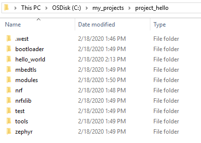
Let's try to run the hello_world sample and verify that everything works as expected.
- Open command line in C:\my_projects\project_hello\hello_world and run
west build -b <board_variant> -d build_manifest- If you've
- Run
nrfjprog --eraseallto make sure the old application is not running - Connect your board to the computer and run
cd build_manifest && west flash - Verify that everything works by checking that the terminal outputs "Hello World!"
2.2 Include files and modify child images
2.2.1 Include header and source files to your project
If your project is getting large, it may be convenient to put some of the functions in different source files. Here I will demonstrate how this can be achieved
- Start by creating a sample containing the elementary files. You can follow the steps under 1.1 Set it up in part 1 of the NCS tutorial series and create a hello world sample, or simply use the existing one, if you've gone through that section.
- In the src folder, create a file named multiply.c, with the following content:
#include "multiply.h"

int multiply(int x, int y){
	return x*y;
}
- Next, in your project folder (e.g. in C:\my_projects\hello_world ) create a folder named include. Then, create the header file multiply.h in the include folder and add the following content to it:
int multiply(int x, int y);
- In main.c you need to include the header file and use the multiply function. Use the code snippet below:
#include <zephyr.h>
#include <sys/printk.h>
#include "multiply.h"

void main(void)
{
	int x = 5;
	int y = 2;
	int result = multiply(x, y);
	printk("%d times %d equals %d\n", x, y, result);
}
- The last step involves specifying the target source and including the header file. This can be done by opening the CMakeLists.txt file and adding the lines as shown in the code snippet below
cmake_minimum_required(VERSION 3.8.2)

find_package(Zephyr REQUIRED HINTS $ENV{ZEPHYR_BASE})
project(NONE)
zephyr_include_directories(include)        #Add this line

target_sources(app PRIVATE src/multiply.c)  #Add this line
target_sources(app PRIVATE src/main.c)
- Follow section 1.2 Build and flash - using SEGGER Embedded Studio and program the hello world sample onto your board. You can choose the same nRF Connect options as in section 1.2, given that you have placed the sample in the same location.
If you would like to use west instead, follow the steps below:
- Open the TM bash command line in C:\my_projects\hello_world and run the command
west build -b <board_variant> && west flash
west build -b <board_variant> && west flash
- Verify that it is working by checking the serial output
2.2.2 Modify device tree and configurations of a child image
It is often the case that an application includes one or more child images, e.g. the SPM sample or the MCUboot, and the need to add configurations or modify the images' device tree might occur. One option is to modify the appropriate files directly, e.g. modify the files C:\Users\<user_name>\ncs\v1.3.0\nrf\samples\nrf9160\spm\nrf9160dk_nrf9160.overlay and C:\Users\<user_name>\ncs\v1.3.0\nrf\samples\nrf9160\spm\prj.conf for the SPM sample. This is not a good practice since this sample might be used by other applications and modifying it directly may cause unwanted behavior for those applications.
Take a look a the section Image-specific variables in the NCS documentation, which proposes a solution to this problem. It says that a variable can get propagated from a parent image (e.g. your application) to a child image (e.g. the SPM sample) by adding the image name as a prefix in front of the variable. This allows you to create conf files and overlay files in your application folder for e.g. the SPM sample by using the variables spm_CONF_FILE and spm_DTC_OVERLAY_FILE respectively.
To enable/disable configurations and modify the device tree for an image with the name <image_name> (for example mcuboot or spm), do the following:
- In your application folder add the following files
- <name_conf>.conf
- <name_overlay>.overlay
- In the CMakeLists.txt file of your application, right below “cmake_minimum_required(…)” add the following:
set(<image_name>_DTC_OVERLAY_FILE
  ${CMAKE_CURRENT_SOURCE_DIR}/<name_overlay>.overlay
)

set(<image_name>_CONF_FILE
  prj.conf
  ${CMAKE_CURRENT_LIST_DIR}/<name_conf>.conf
)
Now you can edit the device tree and enable/disable configurations for your child image through respectively <name_conf>.conf and <name_overlay>.overlay.
In order to follow the steps below, you need a board with a processor that supports secure/non-secure environments. At the time this tutorial was written, only the nRF5340 Soc and the nRF9160 SiP, of the Nordic chips supports this. The board variant must be either nrf5340pdk_nrf5340_cpuappns or nrf9160dk_nrf9160ns.
Let's go through a specific common use-case, disabling logging from the SPM sample:
- Connect the board to your computer and turn it on
- Follow section 1. Your first “Hello World” to create, build, and flash a new and clean hello world sample
- After you've flashed the sample, open a terminal, and reset the chip. Then you'll see the logging from the SPM sample (Secure/nonsecure settings of flash, SRAM, and the peripherals).
- Let's try to remove that log. Add the file spm.conf to <..>\my_projects\hello_world, open it in notepad and add CONFIG_SERIAL=n to it
In this case, the conf file had the same name as the image, but this is not a requirement.
- Modify <..>\my_projects\hello_world\CMakeLists.txt accordingly (remember to add it right under cmake_minimum_required(..)):
cmake_minimum_required(VERSION 3.13.1)

set(spm_CONF_FILE                     # Add this line
  prj.conf                            # Add this line
  ${CMAKE_CURRENT_LIST_DIR}/spm.conf  # Add this line
)                                     # Add this line

include($ENV{ZEPHYR_BASE}/../nrf/cmake/boilerplate.cmake)
include($ENV{ZEPHYR_BASE}/cmake/app/boilerplate.cmake NO_POLICY_SCOPE)
project(NONE)
target_sources(app PRIVATE src/main.c)
- Build and flash the sample in the same manner as explained above. If you're building with SES, in order for the changes in spm.conf to be included, it is necessary to set the nRF Connect options again.
- Connect your board, open a terminal, and reset the chip. All the log from the SPM sample should now be gone, and you should only see the following:
*** Booting Zephyr OS build v2.3.0-rc1-ncs1  ***
Hello World!
3 Create a light intensity controller
This section will show you how to transform your board into a light intensity controller, which can be achieved by using the PWM and the SAADC peripherals and a timer. By checking the input voltage of a pin using the SAADC peripheral, the intensity of an onboard LED can be controlled by varying the pulse width of the PWM signal accordingly. A potentiometer may come in handy but is not mandatory.
3.1 Tools and tips
Before we start creating the project, I would like to present you with some useful tools and tips. If it gets confusing, don't worry, it will make more sense when you start developing.
See the configurations:
There are currently some problems with running menuconfig in the Toolchain Manager, the tutorial will be updated to take this into account
When developing with Zephyr/NCS, you are dealing with a lot of configurations. Here I will show you two ways getting an overview of all the configurations; through menuconfig or through SES.
- In order to run menuconfig, open the command prompt (not bash) from the Toolchain Manager:
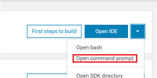
- In the command prompt, redirect to the build folder of hello_world and type
ninja menuconfig
- If you can't find the build folder, follow 1 Your first “Hello World” to generate it
C:\my_projects\hello_world\build>ninja menuconfig
You should then see a window that looks something like this (it will change depending on the board):
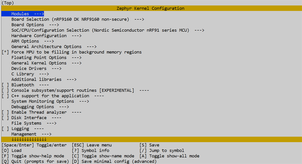
This will get the configurations from the file <..>\hello_world\build\zephyr\.config, and gives you a good overview of the systems configurations. If you modify a configuration, you will see that the .config file will be modified as well. E.g. if you navigate to "Device Drivers→Serial Drivers" and press space followed by the key "S", this will toggle the configuration and disable it. By opening the .config file, you can see that CONFIG_SERIAL is disabled. In menuconfig, click the key "C" to see the name of the configurations (the ones seen in .config).
Let's see how this is done in SES.
- Open the hello_world sample in SES
- In order to see the configurations, click on Project→Configure nRF Connect SDK. A new window "Select target to configure" will pop up, click on "menuconfig". The following window will then appear:
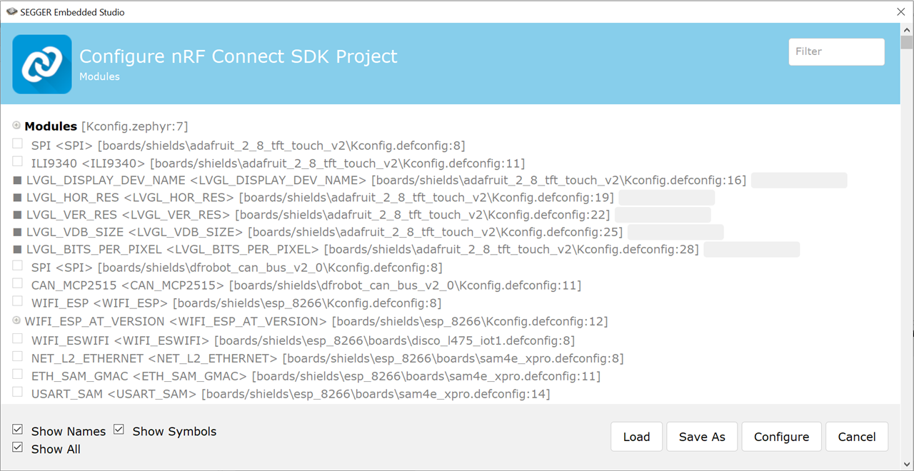
Similar to menuconfig, you can modify the .config file from here, by clicking on Configure after the changes are made. Notice the search bar in the top right corner, which lets you search for particular configurations.
All the changes done to the .config file will be dismissed when the application is rebuilt. In order to make the configurations permanent, do the following:
- Enable the appropriate configurations, either through menuconfig or SES
- Do a diff between .config and .config.old (the file .config.old contains the old configurations and will be generated when changes to .config are made)
- Add the changes to prj.conf
Useful tips for developing an application
→ If you are unsure of how to implement particular peripheral to your project, take a look at the examples and tests provided by Zephyr:
→ If you aren't sure what configurations and node properties a peripheral needs, you should look inside the peripheral's zephyr driver: <sourcecode_root>/ncs/zephyr/drivers/<peripheral>/<peripheral>_nrfx.c (The naming convention may differ slightly from this)
→ Search for "DT_" to see all the Device Tree specific defines the driver uses.
→ Search for "CONFIG_" to see all the configuration-specific defines the driver uses.
→ Take a look at the Kconfig reference in the NCS documentation, which gives you detailed information about all the configuration options from the different NCS projects (nrf, Zephyr, nrfxlib and MCUboot)
→ Opening the ncs folder in an IDE like Visual Studio Code may be helpful:
→ It enables you to perform searches over the whole SDK, which may be convenient if you want to search for functions, variables, macros, configurations or DTS specific stuff.
→ Visual Studio Code comes with an in-built terminal, which makes it possible to build and flash applications directly from the IDE
→ Installing CMake and C/C++ specific extension to Visual Studio Code enables you to browse your code (show definitions and declarations of functions and variables)
3.2 Set it up
Let's set up the light controller application, by creating the necessary files.
- Start by creating a folder named light_controller inside <..>/my_projects and add the files src/main.c, CMakeLists.txt, and prj.conf to it, like we did when creating the hello world application.
- Add the following content to CMakeLists.txt:
cmake_minimum_required(VERSION 3.8.2)

find_package(Zephyr REQUIRED HINTS $ENV{ZEPHYR_BASE})
project(NONE)

target_sources(app PRIVATE src/main.c)
- Add the following config to prj.conf
CONFIG_PWM=y
You may wonder why the configuration CONFIG_PWM_NRFX isn't included, as it is required to build this application and use the Nordic specific PWM drivers. However, it's enabled by default by the Kconfig system for the tested boards.
- Copy and paste the following code into src/main.c
#include <zephyr.h>
#include <sys/printk.h>
#include <drivers/pwm.h>

#define PWM_DEVICE_NAME DT_PROP(DT_NODELABEL(pwm0), label)
#define PWM_CH0_PIN DT_PROP(DT_NODELABEL(pwm0), ch0_pin)


#define PWM_PERIOD 253

void main(void)
{
	printk("PWM Application has started!\r\n");
	u8_t pulse = 0;
	struct device *pwm_dev = device_get_binding(PWM_DEVICE_NAME);
	if (!pwm_dev) {
		printk("Cannot find %s!\n", PWM_DEVICE_NAME);
		return;
	}
        while (1)
        {
                pulse = pulse +10;
                if (pulse > PWM_PERIOD) {
					pulse = 0;
                }
                if (pwm_pin_set_usec(pwm_dev, PWM_CH0_PIN, PWM_PERIOD, pulse, 0)) {
					printk(".");
                }
                k_sleep(K_MSEC(30));
        }
}
You may question what pin the PWM pulses are output on. If you study the code, you can see that channel 0 is used (PWM_CH0_PIN DT_PROP(DT_NODELABEL(pwm0), ch0_pin)). The output pin selected for channel 0 will differ depending on the board. However, for all the tested boards (listed in the introduction), the pin connected to LED 1 is assigned to PWM channel 0. This means that you will see the PWM output on LED 1 for your selected board. E.g. for the nRF9160 Check out the channel 0 pin selection (=P0.02), which corresponds to LED 1 on the DK.
3.3 Build and flash it
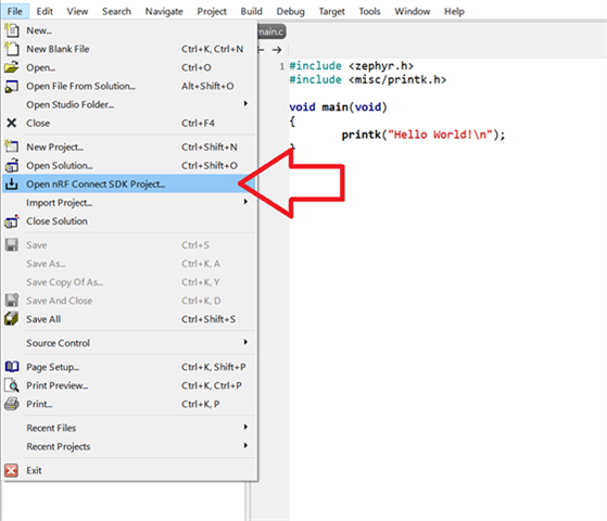
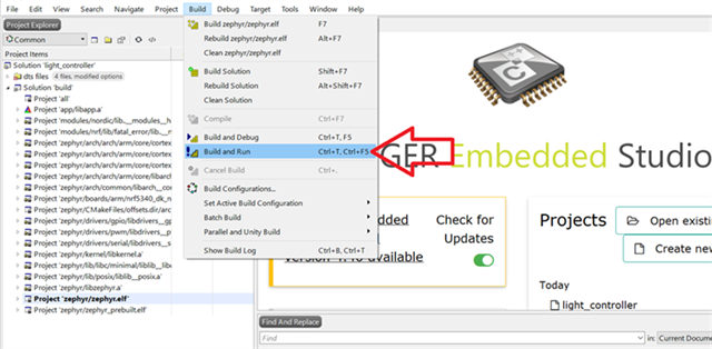
- Open SEGGER Embedded Studio (SES) as explained in section 1.2 Build and flash - using SEGGER Embedded Studio
- Open a new nRF Connect SDK Project:
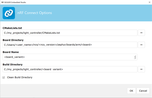
- Set the nRF Connect Options as followed:
- Set ncs_version to v1.3.0
- Eventually, build and run the application
- If you encounter any errors, try running
nrfjprog --eraseallfrom the command line before building and running again
- If you encounter any errors, try running
If the application built and flashed successfully, LED 1 should generate a sawtooth wave, by gradually increasing its intensity before starting back over again.
3.4 Modify the device tree
This section will show you how you can modify and add to the device tree. As mentioned in section 1.4 The Device Tree, this can be achieved by using overlay files, which will override the fields set by dts/dsti files. Specifically, I will show how to use LED 2 instead of LED 1 for the PWM output.
- Add a file named <board_variant>.overlay into <..>/my_projects/light_controller. E.g. if you have chosen nrf9160dk_nrf9160ns as board variant, it should look like this:
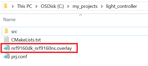
The next step is to set the output-pin for PWM0. In order to see the output, and verify that the application is working, it should be set to a pin that is connected to an onboard LED. Depending on the board, the pin number will vary. Down below is a table that shows the pin number connected to LED 2 for the tested boards.
| GPIO pin connected to LED 2 for the tested boards | |
| <board> | Pin number (pin-number) |
| nRF9160 DK | P0.03 (3) |
| nRF5340 PDK | P0.29 (29) |
- Open the overlay file in notepad and add the lines shown below into it. Use the table above to find the correct pin for your board, and swap
pin-numberwith the value you found.
&pwm0 {
	ch0-pin = < pin-nmumber >;
};
E.g. if you are using an nRF9160 DK, it should look like this:
&pwm0 {
	ch0-pin = < 3 >;
};
The PWM0 node's base position for a chip is set in the DTS file for that particular chip, which can be found in <..>\zephyr\dts\<arch>\<company>. E.g. the base position of PWM0 for the nRF9160 SiP is in the file <..>\zephyr\dts\arm\nordic\nrf9160_common.dtsi.
This node gives a low-level description of the peripheral, and you can see that it is disabled by default. Since most of the peripherals usually are disabled by default for most of the chips, the status field must be set to "okay" in either an overlay file or a DTS board file, in order to be used. E.g. in the file nrf9160dk_nrf9160_common.dts, PWM0's status field is overwritten and set to "okay". In the same file, you can also see that the PWM channel 0 is mapped to pin 2 (LED 1 on the nRF910 DK). The overlay file we made will override the pin mapping for your particular board to pin-number (LED 2 on your board).
- Open a new nRF Connect SDK project and select the same setting used in section 3.3 Build and flash it
- In order for the changes from the overlay file to take effect the project must be re-opened
The ch0-pin field is then transformed into the define DT_N_S_soc_S_peripheral_50000000_S_pwm_21000_P_ch0_pin inside <...>\light_controller\build\zephyr\include\generated\devicetree_unfixed.h and used by the driver pwm_nrfx.c through PWM_NRFX_OUTPUT_PIN()→PWM_NRFX_CH_PIN().
- Eventually, build and flash the application as described in section 3.3 Build and flash it
- Verify that everything works, by checking if LED 2 blinks, reset the board if it doesn't work immediately.
3.5 Add the ADC peripheral
Let's complete the project and add the ADC related part to our project, in order to control the LED intensity.
- Swap the content of <..>\light_controller\src\main.c with the code attached below.
#include <zephyr.h>
#include <sys/printk.h>
#include <drivers/pwm.h>

#if defined(CONFIG_BOARD_NRF5340PDK_NRF5340_CPUAPP) ||  defined(CONFIG_BOARD_NRF5340PDK_NRF5340_CPUAPPNS) || defined(CONFIG_BOARD_NRF9160DK_NRF9160NS) || defined(CONFIG_BOARD_NRF9160DK_NRF9160)

/*ADC definitions and includes*/
#include <hal/nrf_saadc.h>
#define ADC_DEVICE_NAME DT_LABEL(DT_INST(0, nordic_nrf_saadc))
#define ADC_RESOLUTION 10
#define ADC_GAIN ADC_GAIN_1_6
#define ADC_REFERENCE ADC_REF_INTERNAL
#define ADC_ACQUISITION_TIME ADC_ACQ_TIME(ADC_ACQ_TIME_MICROSECONDS, 10)
#define ADC_1ST_CHANNEL_ID 0
#define ADC_1ST_CHANNEL_INPUT NRF_SAADC_INPUT_AIN0

#define PWM_DEVICE_NAME DT_PROP(DT_NODELABEL(pwm0), label)
#define PWM_CH0_PIN DT_PROP(DT_NODELABEL(pwm0), ch0_pin)

#else
#error "Choose supported board or add new board for the application"
#endif

#include <zephyr.h>
#include <device.h>
#include <drivers/gpio.h>
#include <drivers/adc.h>
#include <string.h>
#include <drivers/pwm.h>

#define PWM_MAX 253
#define TIMER_INTERVAL_MSEC 200
#define BUFFER_SIZE 1

struct k_timer my_timer;
struct device *adc_dev;
struct device *pwm_dev;

static const struct adc_channel_cfg m_1st_channel_cfg = {
	.gain = ADC_GAIN,
	.reference = ADC_REFERENCE,
	.acquisition_time = ADC_ACQUISITION_TIME,
	.channel_id = ADC_1ST_CHANNEL_ID,
#if defined(CONFIG_ADC_CONFIGURABLE_INPUTS)
	.input_positive = ADC_1ST_CHANNEL_INPUT,
#endif
};

static s16_t m_sample_buffer[BUFFER_SIZE];

static int adc_sample(void)
{
	int ret;

	const struct adc_sequence sequence = {
		.channels = BIT(ADC_1ST_CHANNEL_ID),
		.buffer = m_sample_buffer,
		.buffer_size = sizeof(m_sample_buffer),
		.resolution = ADC_RESOLUTION,
	};

	if (!adc_dev) {
		return -1;
	}

	ret = adc_read(adc_dev, &sequence);
	if (ret) {
        printk("adc_read() failed with code %d\n", ret);
	}

	for (int i = 0; i < BUFFER_SIZE; i++) {
                printk("ADC raw value: %d\n", m_sample_buffer[i]);
                float val = ((float)PWM_MAX/(float)568)*(float)m_sample_buffer[i];
                printf("Setting pulse to: %f\n", val);
                pwm_pin_set_usec(pwm_dev, PWM_CH0_PIN , PWM_MAX, val, 0);
	}

	return ret;
}

void adc_sample_event(struct k_timer *timer_id){
    int err = adc_sample();
    if (err) {
        printk("Error in adc sampling: %d\n", err);
    }
}

void main(void)
{
    int err;

    //PWM0 setup
    pwm_dev = device_get_binding(PWM_DEVICE_NAME);
    if (!pwm_dev) {
	    printk("device_get_binding() PWM0 failed\n");
	}

    //Timer setup
    k_timer_init(&my_timer, adc_sample_event, NULL);
    k_timer_start(&my_timer, K_MSEC(TIMER_INTERVAL_MSEC), K_MSEC(TIMER_INTERVAL_MSEC));


    //ADC0 setup
    adc_dev = device_get_binding(ADC_DEVICE_NAME);
	if (!adc_dev) {
        printk("device_get_binding ADC_0 (=%s) failed\n", ADC_DEVICE_NAME);
    }

    err = adc_channel_setup(adc_dev, &m_1st_channel_cfg);
    if (err) {
	    printk("Error in adc setup: %d\n", err);
	}

    #if defined(CONFIG_BOARD_NRF9160DK_NRF9160NS) ||  defined(CONFIG_BOARD_NRF5340PDK_NRF5340_CPUAPPNS)
    NRF_SAADC_NS->TASKS_CALIBRATEOFFSET = 1;
    #elif defined(CONFIG_BOARD_NRF9160DK_NRF9160) || defined(CONFIG_BOARD_NRF5340PDK_NRF5340_CPUAPP)
    NRF_SAADC->TASKS_CALIBRATEOFFSET = 1;
    #else
    #error "Choose supported board or add new board for the application"
    #endif
}
This example will use the enum NRF_SAADC_INPUT_AIN0 to set AIN0 to the ADC's positive input pin. Check the table below to see the pin number corresponding to AIN0 for the tested boards:q
| Pin number corresponding to AIN0 for the tested boards | |
| <board> | Pin number |
| nRF9160 DK | P0.13 |
| nRF5340 PDK | P0.04 |
- Then add the following configs to your prj.conf.
CONFIG_ADC=y
Similarly to the case for the PWM configuration, CONFIG_ADC_NRFX_SAADC isn't included. The reason for this is because it will be enabled by default for the tested boards, e.g. if you are using the nRF91 DK it will be set in <..>\adc\Kconfig.nrfx.
- Build and flash your application as we did in 3.3 Build and flash it. Remember to reload the nRF Connect Options, in order for the changes in prj.conf to take effect.
If everything works as intended, you should see that the light intensity of LED 2 depends on the voltage applied to AIN0 (check the table above to see what pin this corresponds to for your particular board). You may attach a potentiometer to AIN0.
If you have any questions regarding this tutorial, please create a ticket in DevZone.
→ Check out the next part of this tutorial series: nRF Connect SDK Tutorial - Part 3
-

Mahendra Tailor
-
Cancel
-
Vote Up
0
Vote Down
-
-
Sign in to reply
-
More
-
Cancel
-

Simon
in reply to Mahendra Tailor
-
Cancel
-
Vote Up
0
Vote Down
-
-
Sign in to reply
-
More
-
Cancel
-

Zeedel
in reply to Simon
-
Cancel
-
Vote Up
0
Vote Down
-
-
Sign in to reply
-
More
-
Cancel
Comment-

Zeedel
in reply to Simon
-
Cancel
-
Vote Up
0
Vote Down
-
-
Sign in to reply
-
More
-
Cancel
Children