


Today we launched the nRF54L15 Tag, a compact, battery-operated tag prototyping platform powered by the ultra-low-power wireless nRF54L15 SoC. nRF54L15 Tag is a flexible platform for prototyping ultra-low-power asset tags, Bluetooth® trackers, and Apple Find My and Google Find Hub compatible products. It includes dual antennas that enhance Google Find Hub's Precision Finding capabilities and provide more robust ranging with Bluetooth Channel Sounding. With its multi-sensor integration, the nRF54L15 Tag also enables quick prototyping of edge AI and Matter applications.
In this blog post, we’ll give a brief feature overview of the nRF54L15 Tag and discuss how to get started with it, including how to build, program and debug a sample on it. Next, we’ll examine ideal use cases and samples available for the nRF54L15 Tag and finally we’ll learn about its expected battery life when operated with a CR2032 coin-cell battery, as well as what additional sensors and buttons can be easily added on the nRF54L15 Tag.
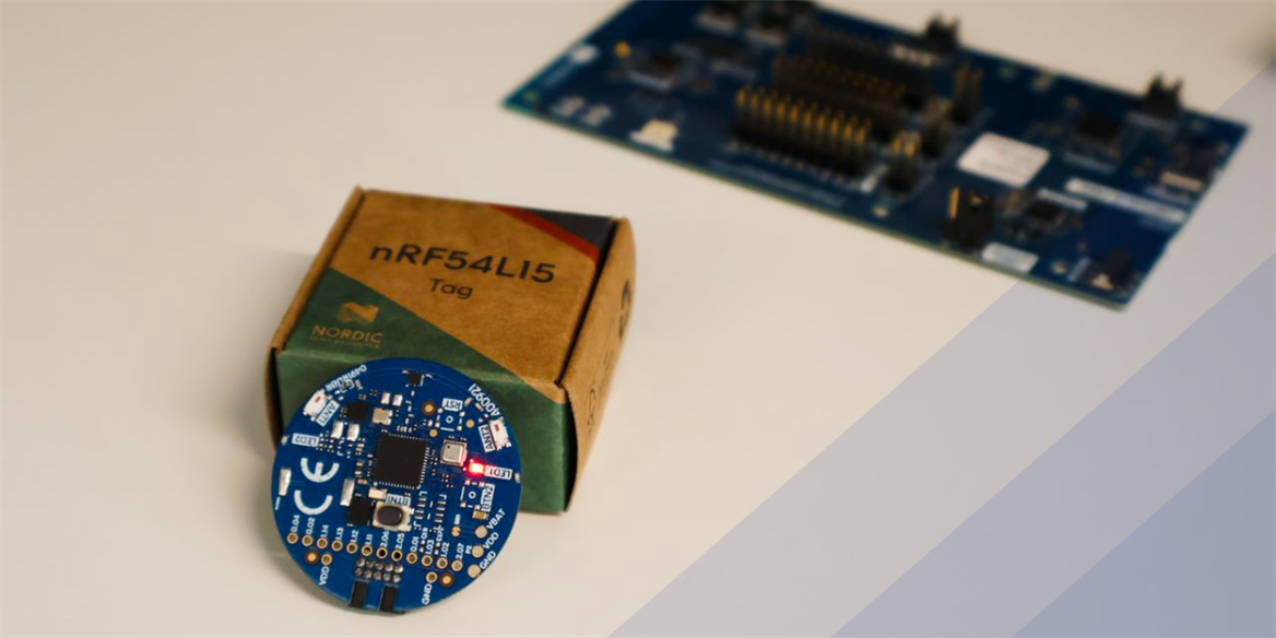
Table of Contents
Feature overview
nRF54L15 Tag’s design is optimized for prototyping and creating proofs-of-concept for compact battery-powered products such as Bluetooth trackers, asset tags, smart wearables and remote controls. As a unique feature, the nRF54L15 Tag has two 2.4 GHz antennas that provide improved robustness for Bluetooth Channel Sounding. The antennas are toggled by a RF switch, and the toggling happens automatically during the Channel Sounding procedure if multiple antennas are configured in the firmware.
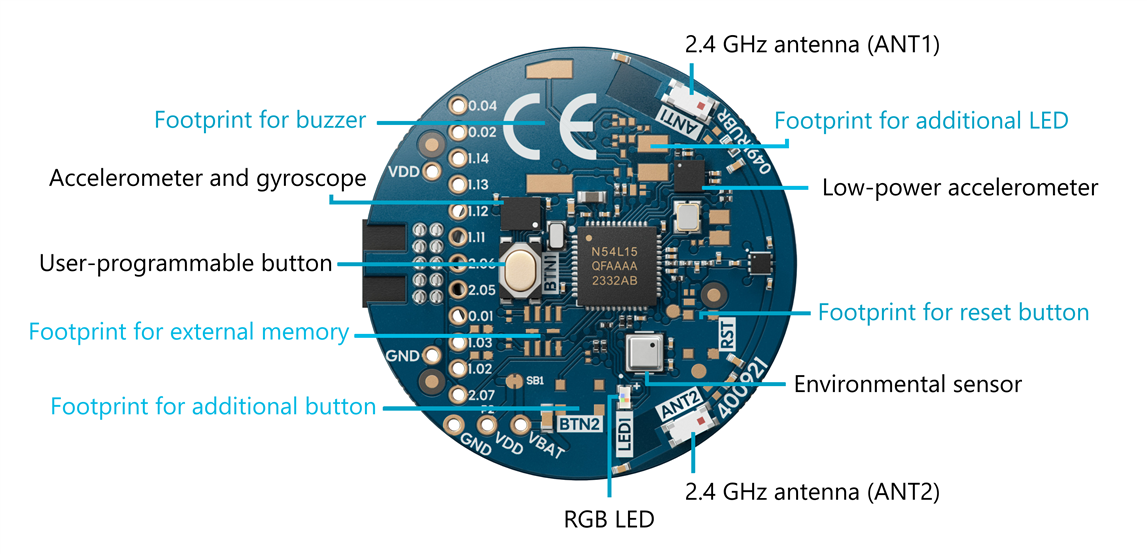
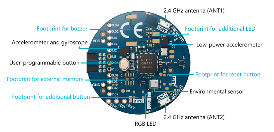
The sensor selection, shown in the sensor overview image below, is optimized for cost-efficiency for prototyping asset tags and Bluetooth trackers. nRF54L15 Tag features a low-power accelerometer for waking up on motion, a six-axis inertial-measurement unit for edge AI training data collection and prototyping products with smart features such as gesture recognition and movement tracking, and an environmental sensor for smart home applications. The design also includes footprints for additional sensors and buttons for expanding the functionality.
Key features of the nRF54L15 Tag are listed below. We will discuss them in detail throughout this DevZone blog.
Ultra-low-power multiprotocol wireless nRF54L15 SoC in QFN package with next-generation 2.4 GHz radio
- Support for the following wireless protocols: Bluetooth® Low Energy, Bluetooth® Channel Sounding, Bluetooth Mesh, Matter, Thread, Zigbee, Aliro, NFC, 2.4 GHz proprietary
- Dual 2.4 GHz antennas providing improved robustness for Bluetooth® Channel Sounding
- Low-power accelerometer (Analog ADXL367) for waking up on motion and extending the battery life
- High-accuracy accelerometer and gyroscope (Bosch BMI270) for edge AI, sensor fusion, wearables, AR/VR and much more
- Environmental sensor (Bosch BME688) for measuring temperature, humidity, air pressure and gas concentration
- 1x User-programmable RGB LED for visual indication, demos and debugging
- 1x User-programmable button for user-input handling
- Powered by a CR2032 coin-cell battery – battery holder included
- Footprints for an additional user-programmable button, reset button, RGB LED, buzzer and external memory for expanding functionality
- Compatibility with Nordic DKs and SEGGER J-Link Debugger for programming and debugging
The image below shows an overview of the sensors and I/O found on the nRF54L15 Tag.
Getting started with the nRF54L15 Tag
Let’s check out what’s found inside the kit for the nRF54L15 Tag and how to get started after unboxing it. The kit for the nRF54L15 tag is available to order from its product page.
For a brief introduction to the nRF54L15 Tag, you can also watch the video below.
What you'll need
- nRF54L15 Tag + CR2032 coin-cell battery – provided in the kit
- nRF54L Series development kit (DK) or an nRF91 Series DK + USB-C cable – ordered separately
- Alternatively: SEGGER J-Link Debugger – for professionals familiar with it
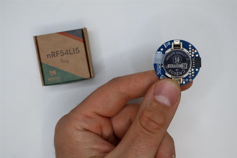
The kit for the nRF54L15 Tag contains the nRF54L15 Tag itself, a CR2032 coin-cell battery and a short intro card. In addition to these, you will need an nRF54L Series DK or an nRF91 Series DK for programming and debugging the tag, and a USB-C cable for connecting the DK to your PC. You may also use any other Nordic DK for this, but nRF54L Series or nRF91 Series DKs are recommended because the voltage is matched for the nRF54L15 Tag without additional setup. You can use for example the nRF54L15 DK or the nRF54LM20 DK.
Once you’ve got these in front of you, you’re good to go. If you have a SEGGER J-Link Debugger and are familiar with using it for programming and debugging, that can also be used with the nRF54L15 Tag.
What's programmed out-of-the-box
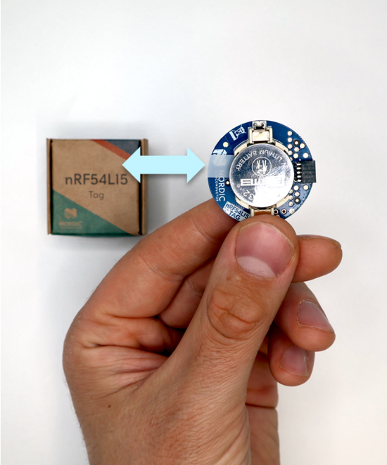
The nRF54L15 Tag includes a CR2032 coin-cell battery in the holder, separated by a small tab from the contacts. To power the tag, pull out the tab. The RGB LED will start blinking, indicating the tag is powered and running the preprogrammed Peripheral LED Button Service (LBS) sample.
Before programming the nRF54L15 Tag with different firmware, ensure the tag is advertising correctly. First, install nRF Toolbox on your phone. The app is available on Play Store and App Store; find more information on its product page via the link above.
Open the nRF Toolbox app and scan for nearby devices. Locate the nRF54L15 Tag advertising as “Nordic_LBS” and connect to it. The LED will switch from blinking to fully lit and change color. Toggling the Light button in the app will change the RGB LED color on the nRF54L15 Tag. This confirms Bluetooth communication works. You can then disconnect and close the app.
Build a sample in the nRF Connect for VS Code extension
Next, we will learn how to build firmware for the nRF54L15 Tag using the nRF Connect for VS Code extension. Open VS Code and make sure you have nRF Connect SDK version 3.3.1 or newer installed. For instructions on installing the SDK and general setup of the nRF Connect for VS Code extension, please see the TechDocs documentation for setting up the SDK and toolchain.
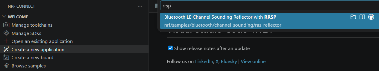
In this blog post, we will use the Bluetooth Channel Sounding Reflector with RRSP sample as the firmware to build and program on the tag.
In nRF Connect for VS Code, select Create a new application > Copy a sample > nRF Connect SDK > v3.3.1 (or newer) > Bluetooth LE Channel Sounding Reflector with RRSP, and then choose a name for the project, or go with the default name. See the screenshot below for the correct sample.
Let’s make one modification before proceeding: add DFU capability to the firmware to enable Over-the-Air (OTA) firmware updates later.
Add the following configs to the prj.conf file in the project to enable MCUboot and OTA DFU:
CONFIG_BOOTLOADER_MCUBOOT=y
CONFIG_NCS_SAMPLE_MCUMGR_BT_OTA_DFU=y
Then, add this into sysbuild.conf – this file needs to be created at the project root, that is, at the same level as prj.conf:
SB_CONFIG_BOOTLOADER_MCUBOOT=y
Finally, for this sample specifically, you will need to restrict the size of the MCUboot partition region to 62 kB and allow combining FPROTECT regions. This is done so that the region can be FPROTECT-protected, as otherwise you will get an error saying that the region size exceeds 62 kB. To do this, create a file sysbuild/mcuboot.conf and add these lines in it:
CONFIG_FPROTECT_ALLOW_COMBINED_REGIONS=y
CONFIG_PM_PARTITION_SIZE_MCUBOOT=0xF800
Once that is done, select Add build configuration and change the Board target in the build configuration to nrf54l15tag/nrf54l15/cpuapp to target the sample for the nRF54L15 Tag.
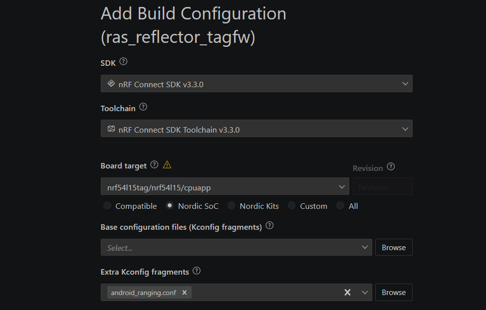
If you have a Pixel 10 phone for testing, add android_ranging.conf to Extra Kconfig fragments. In that case, make the same changes to android_ranging.conf as described above for prj.conf. To test the Reflector sample on the nRF54L15 Tag with a smartphone as the Initiator, visit Evaluating Bluetooth®︎ Channel Sounding with our open-source Android app on Google Pixel 10.
Otherwise, you may leave Extra Kconfig fragments empty and test the application with an nRF54L Series DK as the Initiator by following the Bluetooth: Channel Sounding Initiator with Ranging Requestor documentation. Note that the algorithm in the initiator sample only uses one antenna; for more advanced multi-antenna algorithms, we recommend working with our algorithm partners.
Select Generate and build and wait for the build to finish. For further information about building samples in the nRF Connect for VS Code extension, please see the TechDocs instructions for building an application.
Program the nRF54L15 Tag using a development kit
To program the nRF54L15 Tag, you have three options:
- Plug the nRF54L15 Tag into an nRF54L Series DK or an nRF91 Series DK
- Do a Firmware Over-the-Air (Firmware OTA or FOTA) update
- Use a J-Link Debugger
Let’s go through these options one by one. To program the nRF54L15 Tag using a DK, start by getting an nRF54L Series or nRF91 Series DK in front of you. You may also use any other Nordic DK for this, but nRF54L Series or nRF91 Series DKs are recommended because the voltage is matched for the nRF54L15 Tag in these cases. If you have for example an nRF54L15 DK or an nRF54LM20 DK, either of these will do. You can find all recommended DKs in the Related development hardware section on the nRF54L15 Tag product page.
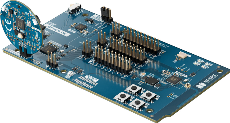
Check the pin alignment tab on the header and plug the nRF54L15 Tag into the DEBUG OUT port of the nRF54L Series DK as shown in the image below.
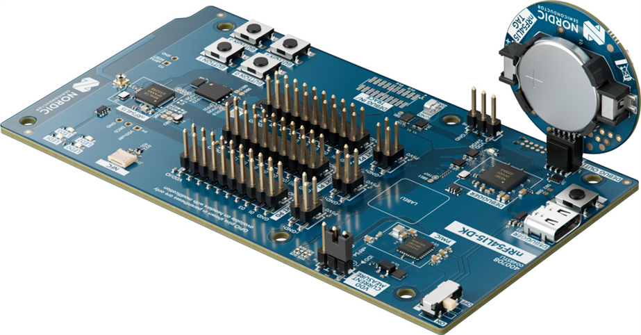
By default, the DK will not power the nRF54L15 Tag through the DEBUG OUT port, so you will need to power it with the CR2032 battery that comes with the kit. See the image below for clarification.
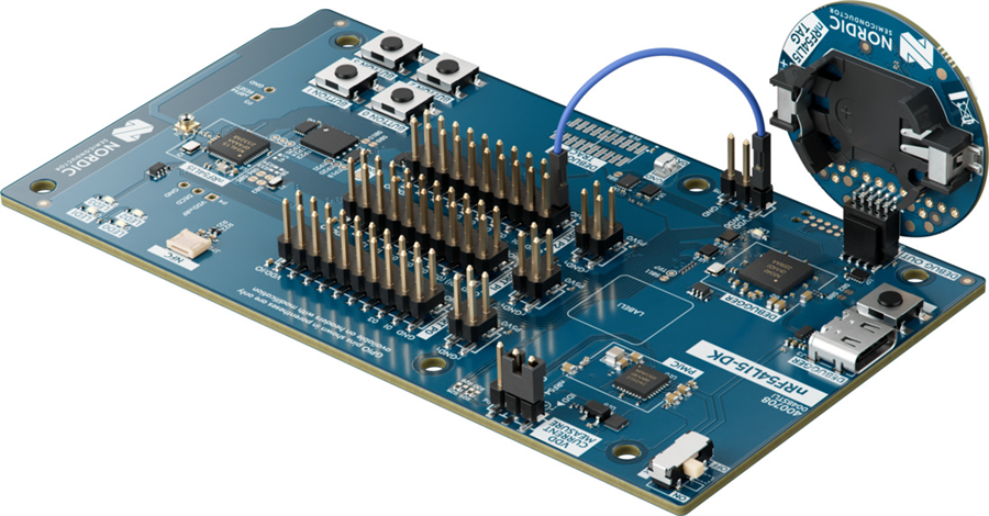
Alternatively, you can power the nRF54L15 Tag without a battery by supplying 3.3V to VDD SWD0, as shown in the image below. You can use VDD:IO from P2 to supply the 3.3V. However, you MUST ensure that the battery is not in place when power is supplied through the DK, as this can cause overheating and damage the nRF54L15 Tag, battery or the DK.
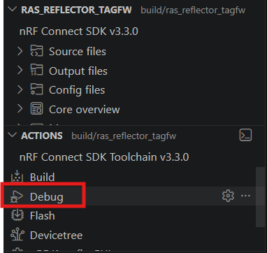
After plugging the nRF54L15 Tag into the DK and powering the tag, you can program it like you would normally program the SoC on the DK. Navigate back to your project in VS Code, select the ras_reflector application in the build folder, and click Flash. The nRF54L15 Tag is now programmed with the Bluetooth LE Channel Sounding Reflector with RRSP sample application.
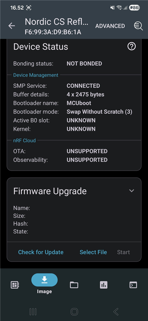
After programming the nRF54L15 Tag, you may detach it from the DEBUG OUT port on the DK. Verify using nRF Toolbox that you can see the tag advertising as “Nordic CS Reflector”.
For further reading, please see the TechDocs documentation for programming and debugging the nRF54L15 Tag and programming an application in VS Code.
Program the tag using OTA DFU
For programming the nRF54L15 Tag Over-the-Air, you will need to have the nRF Connect Device Manager app installed on your phone. The app is available for both Android and iOS.
After installing the app on your phone, send the dfu_application.zip file found under the build folder in your Channel Sounding Reflector VS Code project to your phone. Note that we will assume that you have followed the steps for building the sample application and programming the device using a DK, as given previously.
Open the nRF Connect Device Manager app and select Nordic CS Reflector to connect to the nRF54L15 Tag. Next, navigate to the Image section by tapping the arrow pointing downwards icon (the “download” symbol) at the bottom of the screen. Your app should now look as shown in the image below, and it should say SMP Service: CONNECTED.
Press Select File in the Firmware Upgrade section and choose the dfu_application.zip file that you have sent to your phone. Once it is selected, you may start the OTA DFU by pressing Start.
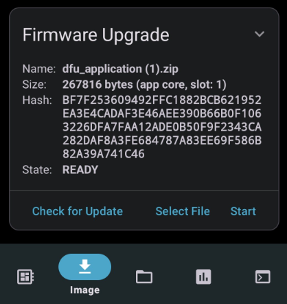
Since the device already runs this firmware, the update process should detect this by comparing hashes and complete quickly, indicated by State: COMPLETED.
To test the OTA DFU further, you may compile the Peripheral LBS sample on your own using steps similar to those for the Channel Sounding Reflector, then update the nRF54L15 Tag’s firmware over the air to the Peripheral LBS sample.
Program the tag using a SEGGER J-Link debug probe
If you are already familiar with using a SEGGER J-Link debugger such as the J-Link PLUS, you can also use that for programming and debugging the nRF54L15 Tag.
For ease of use, we recommend getting the 10-pin Needle Adapter for the debugger, so you can connect it directly to the nRF54L15 Tag.
Debug the tag
Debugging the nRF54L15 Tag is straightforward. Connect the tag to the DEBUG OUT header of an nRF54L or nRF91 Series development kit, then use the nRF Connect for VS Code extension to debug.
Connect the DK to your PC via USB-C and open the nRF Connect for VS Code extension. Select an application, choose the DK in the Connected Devices section, then click Debug to start debugging your nRF54L15 Tag.
Ensure that the tag is powered before doing this by following the instructions in the programming section.
Additionally, the nRF54L15 Tag can also be debugged using a SEGGER J-Link Debugger. This is recommended only if you are already familiar with the tool.
Samples and applications in nRF Connect SDK targeting the nRF54L15 Tag
The following samples and applications in nRF Connect SDK are ideal use cases for making proofs-of-concept with the nRF54L15 Tag. Most samples in nRF Connect SDK targeting the nRF54L15 SoC also support the nRF54L15 Tag. Here, we list the best starting points for prototyping with the tag.
Bluetooth Fast Pair Locator tag
Bluetooth Fast Pair: Locator tag demonstrates a Bluetooth tracker device that is compatible with Google Find Hub and the Android Find Hub app. Bluetooth trackers are typically small tags that can be attached to your belongings – but all kinds of Bluetooth device can employ Find Hub. Devices that are compatible with Find Hub or Find My allow their locations to be securely tracked by their owner using crowdsourced Bluetooth networks for long-range tracking and Precision Finding technologies such as Bluetooth Channel Sounding and UWB for proximity tracking - note that UWB is not natively supported by nRF54L15.
nRF54L15 Tag is especially well-suited for Find Hub compatible trackers due to the fact that it has dual antennas and a low-power accelerometer for waking up the tag. The nRF54L15 SoC also has 1.5 MB of NVM and 256 kB RAM, enabling the nRF54L15 Tag to support both Find Hub and Find My in a single product. Having multiple antennas improves the robustness of Bluetooth Channel Sounding based distance measurement, and this enables the Find Hub app to decide whether to use both antennas for Precision Finding when using Find Nearby functionality.
The Precision Finding feature extends the Google Find Hub specification with ranging capabilities that enable the Seeker device to perform a precise distance measurement with the Provider device. It uses ranging technologies like Bluetooth Channel Sounding to provide accurate proximity information, improving the user experience when locating a missing device.
Precision Finding is currently an experimental feature in the Google Find Hub specification and Bluetooth Channel Sounding is not yet publicly available on it, but it can be experimented with using Android test devices by fulfilling the following requirements:
- The target Android device must run Android QPR3 Beta 2 (January 2026) or a later release.
- The target Android device must have hardware and software support for Bluetooth Channel Sounding (for example, Google Pixel 10)
- Google Play Services must not be enrolled in its independent beta program.
- The primary email account on the Android test device must be registered on Google’s allow list for this feature. To add a test email address to the allow list, contact the Google team to request approval.
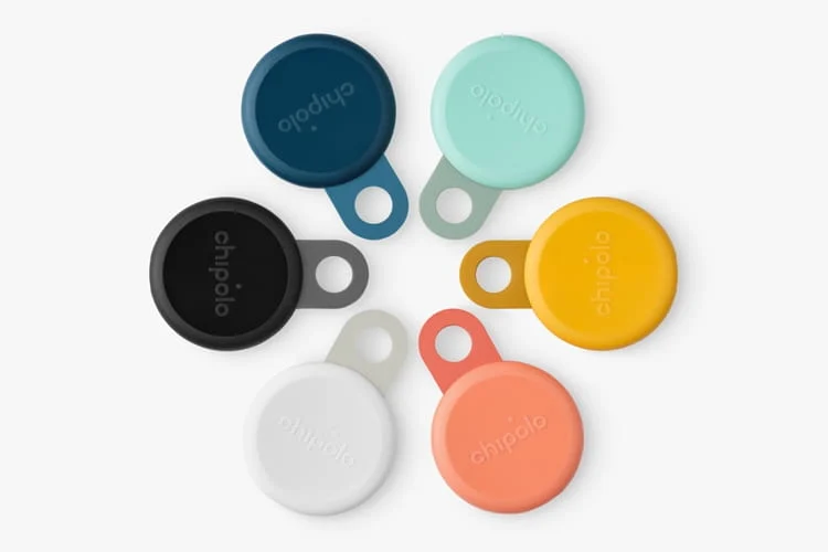
In the image below, you can see Bluetooth trackers developed by Chipolo, based on the nRF54L15 SoC.
Apple Find My network
To develop applications supporting the Apple Find My network, start from this link and follow the instructions to gain access to the Apple Find My SDK. Apple revealed in WWDC26 that they are adding Bluetooth Channel Sounding support in iOS 27 for Find My accessories and to their Core Bluetooth ecosystem.
The requirements for Find My accessories for supporting Bluetooth Channel Sounding are:
- Use Bluetooth 6.3 with Inline PCT Transfer
- Support PBR Mode-0 and Mode-2
- Use T_ICS of at least 100 microseconds
These requirements are met when using nRF54L Series devices with nRF Connect SDK v3.3.1 or newer. The phone must have the N1 chip inside to support Bluetooth Channel Sounding, which means iPhone 17 and iPhone Air series support it.
Bluetooth Channel Sounding
Bluetooth Channel Sounding enables true distance measurement between two devices with sub-meter accuracy, built-in security features and seamless interoperability. It is a connection-oriented point-to-point technology, where one device acts as the Initiator sending the initial tone and processing the ranging algorithm, and the other device acts as the Reflector that simply transmits the signal back to the Initiator.
The nRF54L15 Tag serves as an excellent Bluetooth Channel Sounding Reflector because it is battery-operated, pocket-sized, and features dual antennas that enhance robustness during Bluetooth Channel Sounding ranging. Dual antennas also enable developers to apply more advanced ranging algorithms for improved accuracy and stability. To test the nRF54L15 Tag’s performance with a Channel Sounding enabled smartphone such as the Google Pixel 10, please see the DevZone blog Evaluating Bluetooth®︎ Channel Sounding with our open-source Android app on Google Pixel 10.
The Channel Sounding Reflectors require less processing and less power than Initiators. Typical Reflectors include IoT tags, trackers, key fobs, and wearables, which require a small form factor and reliable, fast RF communication, making the nRF54L15 Tag an ideal prototyping platform for these applications.
The nRF54L15 Tag can also serve as a Bluetooth Channel Sounding Initiator. As mentioned, initiators consume more power because they typically run the algorithm to process ranging data. Therefore the nRF54L15 Tag is better suited as the Reflector, with the Initiator being a smartphone or another embedded device, such as the nRF54L15 DK.
Edge AI gesture recognition
The Edge AI Add-on for nRF Connect SDK offers various applications and samples for edge AI. The nRF54L15 Tag is ideal for capturing training data using its high-accuracy six-axis inertial measurement unit and for prototyping smart features for products like smart rings, remote controls, or wearables. It runs Neuton models that are ultra-tiny edge AI models created from your data with our patented network-growing algorithm.
The Edge AI Add-on includes a gesture recognition application, which supports the nRF54L15 Tag for recognizing gestures such as swiping, shaking, tapping and rotations. Edge AI can also be used for sensor fusion, enabling for example asset tags to improve their positioning or ranging calculations, as well as countless of other smart applications.
Check out this awesome demo video for the gesture recognition application using the nRF54L15 Tag from embedded world 2026.
Matter weather station
The Matter weather station is an application in nRF Connect SDK that demonstrates the use of the Matter application layer to build a weather station that measures weather data using different sensors. The nRF54L15 Tag is ideal for this use case, as it includes an environmental sensor that can measure temperature, humidity, air pressure and gas concentration.
The application uses the user-configurable button on the nRF54L15 Tag to control the device state. The weather station periodically measures temperature, air pressure, and relative humidity. These measurement results are stored in the device’s memory and can be accessed through a Matter controller. The controller communicates with the weather station using the Matter protocol and exchanges data according to the Matter Data Model.
Battery life
A key feature of the nRF54L15 Tag is that it is powered by a CR2032 coin-cell battery. Being battery-powered makes it convenient to demo and prototype PoCs for products with compact designs, as you don’t need to drag along any cables or large batteries.
Battery-operated devices with small lithium coin-cells often raise questions about battery life and peak current capacity. This section presents calculations for typical battery lifetimes during Bluetooth LE advertising, discusses managing peak currents and current draws for optimal battery use, and explains how to measure the nRF54L15 Tag's power consumption.
Average battery life calculations
For battery life calculations of the nRF54L15 Tag, we assume a 220 mAh capacity and 3.0 V nominal voltage for the CR2032 battery. Using these assumptions, we calculate target average currents for 1-year and 3-year lifetimes when doing Bluetooth LE advertising.
Battery: CR2032, Cbat = 220 mAh. Average current targets:
1 year → Iavg = 220 mAh / (365 * 24 h) ≈ 25 μA
3 years → Iavg ≈ 8.4 μA
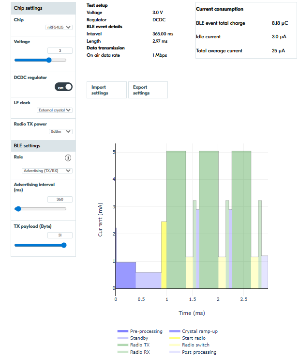
Next, we use the Nordic Online Power Profiler for Bluetooth LE to estimate average current consumption with various settings on the nRF54L15 SoC supplied with 3V voltage. Using Bluetooth LE connectable advertising (TX and RX) at 0 dBm TX power with a 0-byte TX payload yields the following values.
Advertising intervals for each target lifetime:
1 year (≈ 25 μA) → 200 ms
3 years (≈ 8.4 μA) → 840 ms
This means that with a CR2032 at full capacity powering the nRF54L15 Tag, you can do connectable advertising for 1 year with 200 ms advertising intervals and for 3 years with 840 ms advertising intervals on average. Pretty neat!
Increasing the TX payload to 31 Bytes, the values change as follows:
1 year → 360 ms
3 years → 1500 ms
Feel free to test out different settings and TX powers by yourself using the Online Power Profiler. It also supports calculating power consumption for Matter over Thread, which is supported by the nRF54L15 Tag.
Peak currents and continuous current draw
To preserve battery voltage, a standard CR2032 lithium coin-cell battery should not sustain a continuous draw over 3 mA. CR2032s have high internal impedance; heavy continuous current generates internal heat, causing voltage to drop below the nominal 3 V. However, a CR2032 can handle short 1-3 second pulse peak currents of 15 to 20 mA.
In typical Bluetooth LE scenarios, current draws last only 1-3 milliseconds at a time, with the device typically sleeping hundreds of milliseconds between advertising or connection events. Low duty cycles reduce the average current to microamperes, as shown previously.
The average currents during typical Bluetooth LE advertising events are illustrated using current consumption data from the nRF54L15 SoC datasheet, shown in the table below.
|
Active with radio |
Current @ 3.0 V |
|---|---|
|
Bluetooth® LE TX 1 Mbps at 0 dBm |
4.8 mA |
|
Bluetooth® LE TX 1 Mbps at +4 dBm |
6.6 mA |
|
Bluetooth® LE TX 1 Mbps at +8 dBm |
9.8 mA |
|
Bluetooth® LE RX 1 Mbps |
3.4 mA |
With a 100-ms advertising interval, 0 dBm TX power on 1M PHY, connectable advertising, and a 31-byte payload, the nRF54L15 Tag's total average current is ~81 μA per the Online Power Profiler. This is well below the 3-mA limit and will not overload the battery. Even at +8 dBm TX power and 20 ms advertising intervals, the total average current is 554 μA, still below the 3-mA continuous draw.
|
Connectable advertising interval (ms) |
TX Power (dBm) |
PHY |
Payload (B) |
Avg. current @ 3.0 V (μA) |
|---|---|---|---|---|
|
100 |
0 |
1M |
31 |
81 |
|
20 |
+8 |
1M |
31 |
554 |
Note though that the CPU can also perform other processing between Bluetooth advertising. The datasheet indicates that at 3.0 volts, the CPU draws a 2.6 mA peak current (CPU CoreMark® from RRAM with cache).
|
Active with processing |
Current @ 3.0 V |
|---|---|
|
CPU CoreMark® from RRAM with cache |
2.6 mA |
Consider the background processing load in your application when powered by a CR2032. Ideally, processing should occur at low duty cycles to ensure the CPU sleeps most of the time. This also helps maintain low average power consumption and extend the battery life.
Monitoring power consumption and duty cycles is essential to ensure long battery life and maintain the battery at its nominal voltage.
Measuring the power consumption of the nRF54L15 Tag
To measure the average current of the nRF54L15 Tag with an ampere meter, you will need to perform the following steps. These steps are described similarly in the nRF54L15 Tag Hardware User Guide.
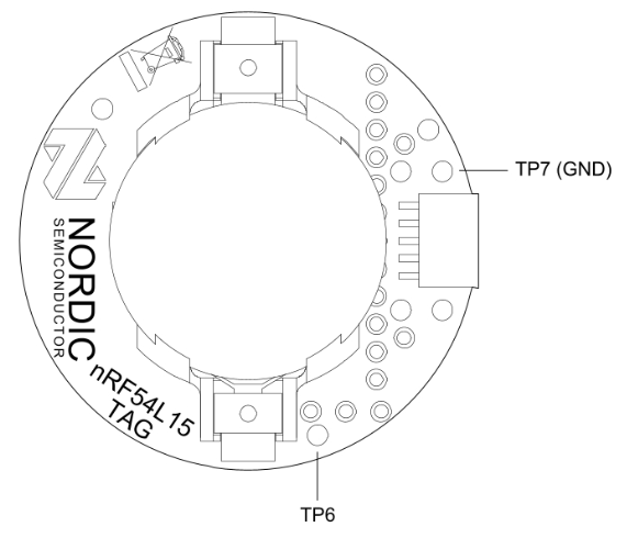
- Cut the solder bridge SB1, shown in the diagram below.
- Power the tag using either of the options described in this previous section of the blog.
- Connect an ampere meter between TP6 and TP7. See the images below
- Set the average timing of the ampere meter to e.g. 1 second or a longer interval.
- Set the dynamic range of the ampere meter between 1 μA and 15 mA for accurate measurements.
Additional sensors and buttons
The nRF54L15 Tag also supports expansion to accessible GPIO on the nRF54L15 SoC. There are footprints for additional buttons and sensors that can be added on the tag: The recommended part numbers are shown in parentheses.
- BTN2 - A user-programmable button (KMT021 NGJ LHS)
- RST - A reset button (KMT021 NGJ LHS)
- LED2 - A user-programmable LED (APHF1608LSEEQBDZGKC)
- Buzzer to act as a speaker (PKMCS0909)
- External memory (MX25R6435FZBIH3)
You may find the footprints marked in the diagrams above and in the hardware files, as well as in the silkscreen. In the schematic (pca20072_schematic_and_pcb.pdf), you may click on the components in the Misc. section to find more information about the specific part numbers for each component, or find them listed in the BoM (pca20072_bom_ems.xls).
These components mentioned above are not provided as part of the nRF54L15 Tag kit in order to keep the design and the kit cost-efficient. The sensors on the nRF54L15 Tag are optimized for the ideal use cases described in the previous sections, but the design allows for expansion through the footprints and accessible GPIO.
Closing
In this blog post, we discussed the features and ideal use cases of the recently launched nRF54L15 Tag and learned how to get started with software development and prototyping with it.
Let us know in the comments what use cases you plan for the nRF54L15 Tag — we love hearing stories directly from developers!
