


Objectives
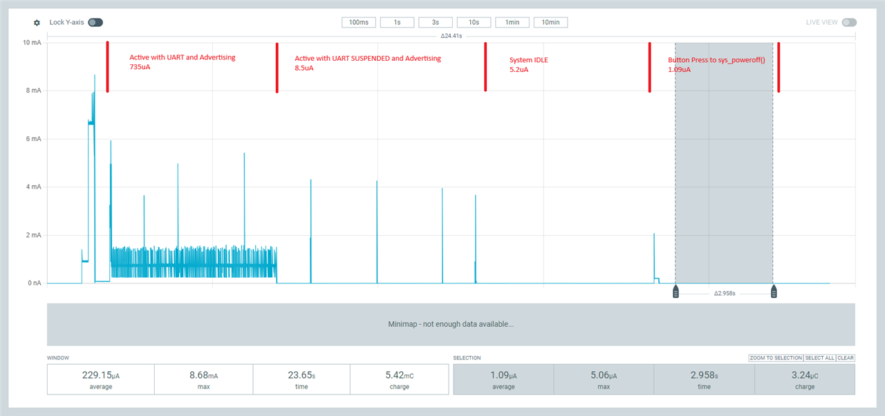
The objective of this blog is to guide the user in the optimization of power on the nRF5340 SoC. The goal is to understand what is needed from a software, hardware, and system level design to minimize the power in your device. This blog is targeted at the nRF5340 SoC, but this information is viable for any nRF52 Series devices except for where we address the use of the dual core in the nRF5340 SoC. A test project was created using the Nordic UART Service (NUS) on the nRF5340 DK and a current measurement can be seen in the PPKII capture below. These results should be the target of your design when completed.
Background
Power optimization is an important element of IoT designs, especially if they are battery powered. The use of nRF Connect SDK with Zephyr RTOS is a powerful tool in the implementation of power management. The interfaces and APIs provided by the power management subsystem in the Zephyr RTOS are designed to be architecture and SoC independent. This enables power management implementations to be easily adapted to different SoCs and architectures. The following sections will describe this subsystem and how you can take advantage of the power saving features when targeting the nRF5340 SoC.
Note this was done in nRF Connect SDK V3.0.0. You can also find information about Power Optimization in the Zephyr documentation https://developer.nordicsemi.com/nRF_Connect_SDK/doc/latest/nrf/test_and_optimize/optimizing/power.html#power-optimization
Software
The power and clock management system in nRF5340 SoC is optimized for ultra-low power applications to ensure maximum power efficiency. The core of the power and clock management system is the power management unit (PMU). The PMU automatically tracks the power and clock resources required by the different components in the system at any given time. To achieve the lowest power consumption possible, the PMU optimizes the system by evaluating power and clock requests, automatically starting and stopping clock sources, and choosing regulator operation modes. There are some configuration options that enable you to implement extra power management policies.
-
Disabling serial logging with the use of CONFIG_LOG=n; CONFIG_SERIAL=n
In asymmetric multiprocessor systems, the most common way for different cores to cooperate is to use a shared memory-based communication. This is done in the nRF5340 using Interprocessor Communication (IPC), which is part of the Zephyr OpenAMP library. The IPC radio firmware allows you to use the radio peripheral from another core in a multicore device. Since the nRF5340 SoC is a dual core device, to minimize power you will need to disable the serial logging in both the application processor and IPC radio peripheral. In the build for the nRF5340 SoC, the IPC_RADIO service subsystem will automatically be built as an additional image in your multi-image build (Please review Sysbuild for multi-image builds). To disable the serial logging, you will need to modify your prj.conf and prj.conf files found in the ipc_radio folder.
For the prj.conf file make the changes seen below.
CONFIG_LOG=n
CONFIG_SERIAL=n
For the prj.conf associated with the ipc_radio, create a folder in your project named sysbuild/ipc_radio.
Your folder structure should look like this:
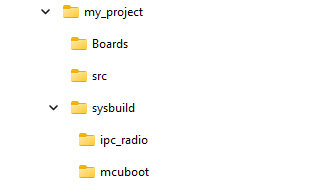
In the ipc_radio folder create a file and name it prj.conf
Then make the modifications to the file as shown below
CONFIG_LOG=n
CONFIG_SERIAL=n
CONFIG_UART_CONSOLE=n
-
Enable the System and Device Power management in your prj.conf file.
The power management features are classified into the following categories: System Power Management, Device Power Management, and Device Runtime Power Management.
There are three configurations needed for system and device power management. These are
CONFIG_PM: This option enables the board to implement extra power management
policies whenever the kernel becomes idle. The kernel informs the
power management subsystem of the number of ticks until the next kernel
timer is due to expire.
Support for the system power management has been removed for the nRF chips, as it is not needed
(https://github.com/nrfconnect/sdk-zephyr/commit/96b38273138f05dd06cf7a58fa361f401e773e5e).

CONFIG_PM_DEVICE: This option enables the device power management interface.  The interface
implemented by device drivers are called by the power management subsystem. This allows
device drivers to do any necessary power management operations like turning off device clocks
and peripherals. Device drivers may also save and restore states in these hook functions.

CONFIG_PM_DEVICE_RUNTIME: This option enables the device power management interface.
Enable Runtime Power Management to save power. With device runtime PM enabled, devices
can be suspended or resumed based on the device usage even while the CPU or system is
running.
Since CONFIG_PM is no longer used by Nordic, you only need to enable Device Power Management and Device Runtime Power Management. To enable these, make the changes to the prj.conf file as seen below.
CONFIG_PM_DEVICE=y
CONFIG_PM_DEVICE_RUNTIME=y
Make sure you also include pm/device.h to your project
#include <zephyr/pm/device.h>
-
System Power Management
The Power Management Subsystem from Zephyr works in conjunction with the nRF5340 PMU. When the system is idle (i.e., no threads are running except the idle thread), Zephyr’s power management subsystem can place the device into low-power states. The PMU then ensures that only the necessary resources remain powered, further reducing energy usage. This is handled automatically by the Zephyr RTOS and does not need to be configured for the lowest System Power.
-
Device Power Management
The system managed Device Power Management (PM) framework is a method where devices are suspended along with the system entering a CPU (or SoC) power state. Device Runtime Power Management involves coordinated interaction between device drivers, subsystems, and applications. It is important to emphasize that the System Device Power Management method has drawbacks and Device Runtime Power Management is the preferred method for implementing device power management. So this blog will continue with the use of the Runtime Device Power Management.
When adding peripherals to your project you will create devicetree bindings for those peripherals. Within your C code you will need to retrieve a device structure for a driver by name by getting its binding. Below is an example of a call to get that device binding. Please refer to the devicetree section of nRF Connect SDK Fundamentals in the DevAcademy for more information.
First start by making a node identifier for the device you are interested in. A node identifier is a way to refer to a devicetree node at C preprocessor time. While node identifiers are not C values, you can use them to access devicetree data in C rvalue form. There are many ways of getting a node identifier. The two most common are by the node label through the macro DT_NODELABEL() and by an alias through the macro DT_ALIAS(). Others are also listed below.
/*Option 1: by node label*/
#define MY_SERIAL DT_NODELABEL(serial0)

/*Option 2: by alias*/
#define MY_SERIAL DT_ALIAS(my_serial)

/* Option 3: by chosen node */
#define MY_SERIAL DT_CHOSEN(zephyr_console)

/* Option 4: by path */
#define MY_SERIAL DT_PATH(soc, serial_40002000)
Once you have the node identifier, retrieve a device binding by using DEVICE_DT_GET();
const struct device *uart_dev = DEVICE_DT_GET(MY_SERIAL);
Once you have the binding you can set the device power state by using pm_device_action_run();
int pm_device_state_set(conststructdevice*dev, uint32_t device_power_state,pm_device_cbcb,void*arg)
there are 4 action states available in the pm_device_action_run() call
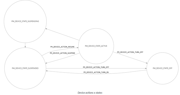
PM_DEVICE_ACTION_SUSPEND
device is in SUSPEND power state

The driver will perform the necessary steps to suspend the device, such as uninitializing
hardware or switching to a low-power state. It is the responsibility of the device driver
to save any necessary context before suspending and to restore it upon resume,
as the power management subsystem itself does not handle device-specific context
preservation

PM_DEVICE_ACTION_RESUME
device is in RESUME power state

 When this action is triggered, the power management subsystem notifies the device
 driver (via its PM action callback) that the device should transition from a suspended
 (low-power) state back to an active state. It is then the responsibility of the device
 driver to perform any hardware-specific steps needed to resume normal operation, such as
 reinitializing hardware or restoring context.

PM_DEVICE_ACTION_TURN_OFF
device is in TURN OFF power state

This action is typically triggered by a power domain, not directly by the device or
application. After this action, the device transitions to the PM_DEVICE_STATE_OFF state,
where its context is lost and power is removed.

PM_DEVCIE_ACTION_TURN_ON
device is in TURN ON power state

This action is typically triggered by a power domain, not directly by the application
or device itself. This action transitions the device from the PM_DEVICE_STATE_OFF state to
the PM_DEVICE_STATE_SUSPENDED state.
Below is the Device Actions and States of the Device Power Management Subsystem. This method is used to track power states of a particular device. It is important to emphasize that, although the state is tracked by the subsystem, it is the responsibility of each device driver to handle device actions(pm_device_action) which change device state.
By following our example from above the code to set the UART to a low power state would look like the following:
err = pm_device_action_run(uart, PM_DEVICE_ACTION_SUSPEND);
note: You must call uart_rx_disable() and wait for the UART_RX_DISABLED event before calling pm_device_action_run(uart, PM_DEVICE_ACTION_SUSPEND). If you suspend the UART while RX is still enabled, it can cause assertion failures or crashes. Wait for the callback/event indicating RX is disabled before suspending the device.
err = uart_rx_disable(uart);
        __ASSERT(err == 0, "Failed to disable uart rx");
-
Disable unused peripherals
Based on the device tree of the board you are using; certain peripherals are enabled by default. If you are not planning on using those peripherals in your project you can disable them in an overlay file.
For example;
On the nRF5340 DK both UART0 and UART1 are enabled. If you do not plan on using UART1 in your design write an overlay file to disable UART1 as follows:
Create a file named nrf5340dk_nrf5340.overlay and place it in your project directory.
The file would need to contain the following
nrf5340dk_nrf5340.overlay
&uart1{

    status="disabled";
};
More information on "Setting Device Tree Overlays" can be found in the Zephyr documentation.
-
Setting Device into SYSTEM OFF State
System OFF is the deepest power-saving mode available on Nordic Semiconductor devices. In this mode, the system’s core functionality is powered down and all ongoing tasks are terminated. Only specific wakeup sources remain active, and the device typically performs a system reset upon wakeup. One or more RAM sections/blocks can be retained, depending on configuration in RAM retention registers.
You can enter System OFF by calling
sys_poweroff();
In this state you can wake from various sources including
- DETECT signal from GPIO
- ANADETECT from LPCOMP (if available)
- SENSE from NFC (if available)
- Valid USB voltage on VBUS (if available)
- Debug session start
- Pin reset
Note: When using a GPIO as a wake source, be sure to utilize sense-edge-mask in your overlay. It controls which GPIO pins use the hardware "sense" mechanism for edge detection, by enabling the use of GPIOTE PORT events instead of dedicated GPIOTE IN channels. The hardware sense mechanism is specifically designed for low-power operation, especially in sleep modes. When using the sense mechanism, the device can remain in a low-power state and still detect pin changes, whereas using GPIOTE IN channels requires more active hardware resources, which increases current consumption.
Add this to the nrf5340dk_nrf5340.overlay for our example of using SW1 as the sense wake pin.
&gpio0 {
    sense-edge-mask = <0x01800000>; /* 1<<24 | 1 <<23 */
};
System
Some configuration options will cause a higher internal voltage to be requested, which will be observed as an increase in power consumption.
- By default, the application core frequency is set to 64Mhz and is managed by the PMU as mentioned in the prior section. Keep in mind if you set it to a higher frequency you will see an increase in power. Setting the frequency of the application core's clock to 128 MHz, see Application core frequency scaling. The increased power consumption in this mode will also be observed when the CPU is sleeping, i.e. after executing the WFI (wait for interrupt) or WFE (wait for event) instructions.
- You can set a device power state for the QSPI when not in use, as described in the prior section on device power management. Under normal use the QSPI interface operates between 6-96Mhz. The lower the frequency of operation the lower the power consumption of this peripheral. The QSPI clock frequency can be set in the device tree using the sck-frequency property
- The need to increase the TX power to +3dB you will need to request additional voltage. Requesting additional voltage on the VREGRADIO supply using VREQCTRL — Voltage request control to increase the TX power will add to the overall power consumption of the nRF5340
- When using the GPIOTE in a PORT or IN Event the Latency register makes it possible to trade off detection speed versus power.
- The nRF53 devices are optimized for running at 3V (although the nRF5340 will accept 5.5V). None of the internal circuitry runs at these voltages except the GPIO, so running at lower voltages will not result in reduced power consumption
- By default, the high voltage regulator is configured to also source external components from the VDD pin. To save power this feature should be disabled. For details, see High voltage mode
- All regulators operate in LDO mode by default. DC/DC mode can be enabled independently for each regulator. The advantage of using a regulator in DC/DC mode is that the overall power consumption is reduced.
Hardware
- Be aware that single-pin GPIOTE interrupts may use more power than Port GPIOTE interrupts depending on the scenario. (see note in SYSTEM OFF section of Blog)
- The default (from reset) state of all GPIO is as a disconnected input. Unless you’ve previously configured them to something else, you can leave unused pins in their default state and physically disconnected to draw no current.
Debugging
- When debugging the nRF5340 you can use thread aware tools like Ozone that will help determine thread status and determine if you are residing in an idle thread. There is a good tutorial on Thread aware debugging that I recommend to review.
- Use the right tool to measure your current. Use the online power profiler and Product Spec numbers to estimate your average current. Use the PPK-2 to measure it. With the PPK-2 you can log for long periods of time. Please review this blog for reference.
- Make sure to power your design with a battery when measuring current, since a power supply may introduce unknown variables.
- Here’s a list of the most common power scenarios and how to recognize them.
- You think the part is a PM_DEVICE_ACTION_SUSPEND mode, but the part is drawing much more than 10 uA.The part hasn’t set all peripherals in a DEVICE_ACTION_SUSPEND mode and something has been left running. Make sure your low power procedure actually places all peripherals in a low power state. It is also recommended that you make sure that the device driver you are using implements the PM API (Nordic Peripheral drivers all Implement the PM API). While using the PPK-2 you should be able to see the SOC in a low power state and consuming less than 10uA while advertising.
- You think you’re in SYSTEM_ON mode with the CPU off but you measure 100’s of uA.You’ve left a peripheral on, maybe intentionally. If you left logging enabled through the UART, this will also use this amount of current. Turn off UART logging in the prj.conf file in favor of RTT. RTT will not use current unless the debugger is connected.
- QSPI/External Flash Not in Low Power. If QSPI or external flash is not put into deep power down or is left enabled, it can significantly increase current. Either “disable” the peripheral in the devicetree or use the power management API’s to place it in a SUSPEND mode.
- Floating or Undefined GPIOs: Unused or undefined pins can draw current if not properly configured (e.g., left floating). It's best to define unused pins as outputs or enable pull resistors
SUMMARY
SUMMARY
In summary, after reading this blog you should be able to optimize the power in your nRF5340 design using NCS. We did this by using the following methods:
- Disabling the serial Logging
- Enabling the Power Management in Zephyr
- Setting the peripherals into a desired pm_mode
- Disabled unused peripherals
- Checked HW and System settings
- Checked your results using a PPK2 or Dynamic Power Analyzer (OTII, Keysight, etc)

Top Comments
-

WesC
-
Cancel
-
Vote Up
0
Vote Down
-
-
Sign in to reply
-
More
-
Cancel
-

hatt-mazley
in reply to WesC
-
Cancel
-
Vote Up
0
Vote Down
-
-
Sign in to reply
-
More
-
Cancel
-

WesC
in reply to hatt-mazley
-
Cancel
-
Vote Up
+1
Vote Down
-
-
Sign in to reply
-
More
-
Cancel
Comment-

WesC
in reply to hatt-mazley
-
Cancel
-
Vote Up
+1
Vote Down
-
-
Sign in to reply
-
More
-
Cancel
Children