

FYI: The video above shows a similar test as this blog post, just using two nRF52840 DKs and two nRF21540 DKs. The blog post uses one nRF52840 DK and two nRF21540 DKs. One of the reasons we did multiple tests was to verify the range results in different conditions.
Introduction
One factor that is important to engineers and software architects that use the Bluetooth LE protocol is range. This blog looks at the max distance that can be achieved using two nRF52840 DKs and one nRF21540 DK at the standard Bluetooth Low Energy 1M PHY.
To be able to truly understand this test, you need to understand two things.
- Path Loss
Below is the text used to explain path loss from my older blog for testing long range with Coded PHY. The older post will soon be deprecated as it is based on our older nRF5 based SDK, but all the theoretical points regarding radio waves are still valid from that old post.
Path loss is the reduction in power density that occurs as a radio wave propagates over a distance. The primary factor in path loss is the decrease in signal strength over distance of the radio waves themselves. Radio waves follow an inverse square law for power density: the power density is proportional to the inverse square of the distance. Every time you double the distance, you receive only one-fourth the power. This means that every 6-dBm increase in output power doubles the possible distance that is achievable." (Electronic Design)
But in the real world, the path loss is a little bit more than the ideal air path loss. This is due to the precipitation, humidity, reflected signals, and so on, which deteriorates the signal more in the path.
- Antenna Performance
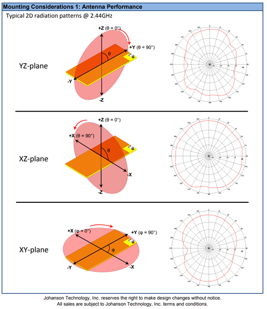
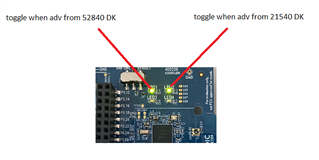
The antenna performance used in the test equipment is very important to get better results and also better interpret the data obtained. As you can see in the antenna gain chart below for the nRF21540 DK, the antenna gain performance is best in the XZ plane (see this external article for more info).. The white box on the yellow PCB is the antenna. Considering there can be potential loss within the PCB of both the nRF52840 DK and nRF21540 DK, the Z+ plane is the best plane to test the DKs.
The best communication and range is achieved if the DKs are aligned (in terms of direction the face) like below for the test purpose.
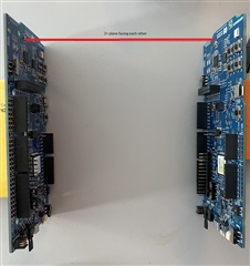
It was best to have a clear line of sight over the test range, so I chose to have the setup lifted up to 2.5m (8.2ft) high to achieve this. I tried to make sure that the Z+ plane of all testing DKs face each other during the entire test path.
Testing Bluetooth LE unidirectional communication (Advertising-Scanning)
Bluetooth LE advertisement and scanning is unidirectional, i.e. the advertiser does not expect an acknowledgment packet from the scanner for this communication to work. The main point is to test the max range when the scanner can still receive advertisement packets from the advertiser. This way of communication eliminates the Link Layer controller implementation limitations that can affect the max range (more on that later in the section where we test the range in a Bluetooth LE connection). Let us now start digging into the details of the test setup for advertising/scanning max range.
Test Setup and Equipment
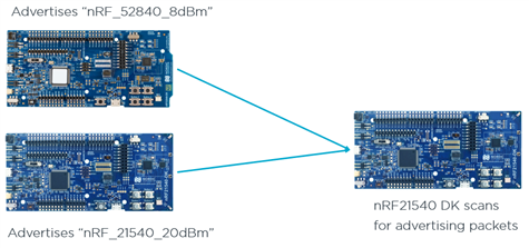
1 X nRF52840 (PCA10056) (Advertiser advertising full name "nRF_52840_8dBm")
1 X nRF21540-DK (PCA10112) (Advertiser advertising full name "nRF_21540_20dBm")
1 X nRF21540-DK (PCA10112) (Scanner scanning for the above two advertisers)
Firmware: nRF Connect SDKv1.8.0
IDE: Visual Code Studio (v1.65.1 or later): nRF Connect Extension pack installed.
Scanner is modified Bluetooth LE Central UART.: (nRF_21540_DK) Scanner_filter_match_adv_name.zip
The scanner is the Bluetooth LE central sample in nRF Connect SDK which is modified to enable the scan filter match for advertisers sending full device names which are "nRF_52840_8dBm" and "nRF_21540_20dBm". The LEDs on the scanner toggles with reception of the data from the advertisers under test. When the received advertising data is "nRF_52840_8dBm", then LED1 toggles its state. Similarly when the received advertising data is "nRF_21540_20dBm", then LED2 toggles its state. This is done so that we use these LEDs as a visual aid to see if the scanner is still receiving the packets from the advertisers of our interest. If you have the scanner DK connected to the PC, then you can see the logs over the serial COM port as shown below Logs on the scanner side show the peer device name and the advertising connection type.
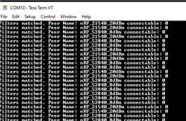
The TX power on the radio for scanner is set to 0dBm and the nRF21540 RF FEM power amplifier gain is set to 20dBm. That is the total TX power should be (0 dBm + 20dBm =) +20dBm and this should be visible from the logs at the time of device bootup initialization It is worth noting that since the scanner is using nRF21540DK, the LNA will always improve RX sensitivity by roughly 5 dB compared with the nRF52540 DK. There is no bypass of LNA. This extra RX sensitivity will be same when receiving advertising packets from both nRF52840DK and nRF21540DK, That is, the range achieved is still comparable in terms of transmitter capabilities . Build and flash the scanner into nRF21540 DK and carry this scanner along with you while moving away from the fixed advertisers. Do not forget that the best reception is achieved when holding the scanner with its Z+ plane facing towards the fixed advertisers. Build and flash (into 21540_DK) the scanner as mentioned in the application build tutorial. The way I tested was that I walked/drove 100 meters at one time and then held the scanner with its Z+ plane facing the advertisers to see if both LEDS 1 and 2 are still blinking to confirm that the adv packets are still visible at this point. If yes, then I move even farther and repeat the process until one of two LED stops blinking completely. At this point we know that we have crossed the range where the scanner is unable to receive any advertising packets from the advertiser which links to the LEDs that stops blinking.
Advertiser is modified Bluetooth LE Peripheral UART: (nRF_52840_8dBm) adv_nRF_52840_8dBm.zip
Advertiser is very simple, it sets the device name to "nRF_52840_8dBm" and the radio TX power to +8dBm and broadcasts full device name as its advertising data. It also advertises the UUID of the NUS (Nordic UART Service) as the additional scan response data, but we do not use this additional data in this test, The LED 1 on the advertiser is blinking when the device is advertising and the LED blink frequency is fixed. The LED 1 blink frequency is NOT the same as the advertising interval. This LED blinking is just to have a visual aid for us to know that the advertiser is properly advertising.
Have the advertiser flashed with above project fixed at the position with its Z+ plane facing towards the direction you will be moving away with the scanner in hand. I walked hundred meters away from the advertiser, stopped and raised the scanner DK up with its Z+ plane facing the direction of the advertisers. If LED 1 on the scanner you are holding is still toggling its state, then it is still able to receive the packets from our advertiser. Then you can walk more 100 meters away to stop and test if the scanner LED 1 is still toggling its state. You can repeat this process until you see that the scanner LED 1 is not toggling anymore. This is a visual proof for us to know that the scanner is not able to receive anymore packets from out advertiser. Then you know that you have exceeded the range of communication between the fixed advertiser and the scanner in your hand.
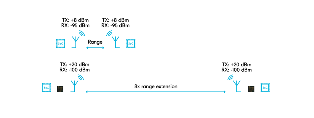
With max SoC output of +8dBm, I was able to get 1.62km of range using unidirectional communication on nRF52840 DK kit.
Modified Bluetooth LE Peripheral UART: (nRF_21540_20dBm) adv_nRF21540_20dBm.zip
The advertiser is very simple. It sets the device name to "nRF_21540_20dBm" and the radio TX power to 0dBm and the FEM PA gain is set to 20dBm. The total TX power is then +20 dBm for this advertiser. The broadcast data uses the full device name as its advertising data. The LED 1 on the advertiser is blinking when the device is advertising and the LED blink frequency is fixed (and NOT same as advertising interval). The scanner should toggle LED2 when it receives advertising packet from this advertiser.
Have the advertiser flashed with above project into the nRF21540 DK and fixed at one position with its Z+ plane facing towards the direction you will be moving away with the scanner in hand. I drove hundred meters away from the advertiser, stopped and raised the scanner DK up with its Z+ plane facing the direction of the advertisers. If LED2 on the scanner you are holding is still toggling its state, then it is still able to receive the packets from our advertiser. Then you can drive more 100 meters away to stop and test if the scanner LED2 is still toggling its state. You can repeat this process until you see that the scanner LED2 is not toggling anymore. This is a visual proof for us to know that the scanner is not able to receive anymore packets from out advertiser. Then you know that you have exceeded the range of communication between the fixed advertiser and the scanner in your hand.
With the nRF21540 DKs, I achieved 4270 meters of range! Even though the test conditions were not perfect that day, the results are not disappointing.
Conclusion:
| Test scenario | Range (meters) |
| 1x nRF52840 DK at TX=8 dBm and 1x nRF21540 DK receiving | 1620 |
| 2x nRF21540 DK at TX=20dBm | 4270 |
With the nRF21540 DK advertising with a total TX output of +20dBm, we achieved around 4.27 km range. With the nRF52840 DK advertising with a total TX output of +8dBm, we achieved 1.62 kms of range. The difference in TX power between the two was (20 - 8 =) 12 dBm. The range improvement we got was 4.27/1.62 = 2.635 times. As I mentioned earlier while describing path loss that every 6-dBm increase in output power doubles the possible distance that is achievable. So with +12 dBm of increased TX power the improvement in range should have been 4 times. But this can only happen in more ideal condition than what could be achieved outside in different landscapes. There are many other different factors like humidity, visibility, reflections, refractions and absorption by different material (like water) that affects the radio waves which in turn affects the range.
Testing range Bluetooth LE Connected role
Test Setup and Equipment
You can test range of nRF52840 Peripheral to nRF52840 Central or nRF21540 Peripheral to nRF21540 Central and you need below setup to test.
2 X nRF52840 (PCA10056) (One for peripheral and one for central) : > nRF52840.zip
2 X nRF21540-DK (PCA10112) (One for peripheral and one for central) : > 4747.nRF21540.zip
The Zip file attached contains the HEX files for the peripheral and central.
- To test the range between two nRF52840 DK with TX power of 0dBm, flash the kits with the hex files from nRF52840.zip\TX_0dBm\
- To test the range between two nRF52840 DK with TX power of +8dBm, flash the kits with the hex files from nRF52840.zip\TX_8dBm\
- To test the range between two nRF21540 DK with a total TX power of 0dBm, flash the kits with the hex files from nRF21540.zip\0dBm\
- To test the range between two nRF21540 DK with a total TX power of 20dBm, flash the kits with the hex files from nRF21540.zip\Pos20dBm\
Some of the details about the peripheral and central are as below
- Peripherals before the connection are advertisers with the name "Nordic_UART_Service" as full device name and have NUS UUID as scan response data.
- LED1 blinks when the device is advertising.
- LED2 is ON when there is a connection with the central, LED2 is OFF when there is not connection.
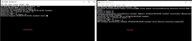
- The UART logs shows something like below when booting up and when a connection is established.
- Central before the connection are the active scanners looking for a scan match filter full device name "Nordic_UART_Service". Once the scanner get an advertisement packet that matches the scan filter, it immediately sends a connect request to the advertising device.
- No LEDS are are on while scanning.
- LED2 is on when in connection.
- The below is the logs when flashing peripheral and central hex files with TX = 8dBm output power.
- The range I got for the 0dBm on nRF52840 DK - nRF52840 DK with the attached hex files was around 597m.
- The range I got for the 8dBm on nRF52840 DK - nRF52840 DK with the attached hex files was around 700m.
- The range I got for the 0dBm on nRF21540 DK - nRF21540 DK with the attached hex files was around 610m.
- The range I got for the 20dBm on nRF21540 DK - nRF21540 DK with the attached hex files was around 900m.
The explanation of why we get reduced results in connected roles in 1M/2M PHY in BLE is due to the architectural choice on the range delay in we have in our Bluetooth LE Link Layer. More on this can be read in FAQ.
FAQ
Q) Why is the test done outdoor?
A) We cannot generalize observations and conclusions with the results obtained indoors since the radio waves are influenced by so many other factors of reflection/refraction and absorption from many different kinds of material (each with different properties around radio waves) that is used in construction or just lying indoors. The aim of this range experiment was to check and compare the maximum range that can be achieved with nRF52840 and nRF21540 DKs compared to the theoretical max range.
Q) Do we get significantly higher range if we use CODED PHY in this experiment?
A) Yes, using coded phy instead of 1M phy should give much farther range than the one observed here. Note that coded phy range has not been tested here. There are other samples to test that and questions regarding coded phy are out of scope in this blog post.. Also note that depending on region and protocol used, there is a maximum regulatory TX output power limit (see chart mentioned in range extenders page for more info. Please note that certain countries' regulatory have a limit on the maximum output power that can be used using coded phy.)
Q) How does the use of internal RC or external XTAL source clock affect distance?
A) One cannot use internal RC for HFCLK if you want to use RADIO with Bluetooth LE. The accuracy of the clocks should not affect the range in itself but might affect the frequency of packet errors at the receiver side which indirectly affects the range.
Q) Can I used the hex files attached in the zip files instead of compiling the applications provided?
A) Yes, that is the best way to compare your results with mine. Depending on the terrain you test in, there can be lots of other variables that can affect the range. One of the most important factors is to have line of sight between the advertiser and the receiver. So, yes, use the hex file to flash to the device and do a quick range test if you want to quickly validate this.
Q) These results are achieved based on nRF Connect SDK, are these results compatible with long range results that can be achieved based on nRF5 SDK?
A) Theoretically, the results should be comparable with Advertising/Scanning roles range test. But there are still implementation differences in the Bluetooth LE controller link layer in both setups (nRF5 SDK uses the SoftDevice, whereas this example uses the SoftDevice controller in nRF Connect SDK) that might give little bit varied results. I am quite certain that the connected roles results can vary between nRF5 SDK and nRF Connect SDK due to the above mentioned implementation difference in the link layer implementation.
Q) Why do you get less range in the connected roles?
A) Connected roles work based on the acknowledgement from the peer. In the connected roles, the scanner becomes central and advertiser becomes peripheral right after the scanner sends a connect request for the advertising packet it received from our connectable advertiser. That is every packet needs to be acknowledged from the peer to move on to the transmission of next packet. In the connected roles the RADIO is in the reception mode (just after sending a packet) to listen to the acknowledge from the peer only for a limited time window. If the peer does not respond to with an acknowledgement within that time window, then it is considered as a packet miss since our device is not listening anymore. This is because of the very fixed timings on when the peers can send and receive in the connected roles. The propagation of radio waves takes time (it can travel approximately 300 meters in 1us). The link layer in our Softdevice Controller has added an extra time (also called range delay) for the reception to consider that the acknowledgement from the peer can take time to receive even though the peer has responded in time. That is, the receiver needs to keep the radio ON for this extra amount of time just for the propagation delays to be taken into consideration. This hardcoded extra time (range delay) the the receiver listens to in connected roles, also limits the acceptable propagation delays and hence the range. This limits the maximum range on 1M/2M PHY connected roles to be around 800m.
Q) Why do you have to have a hard limit on the range delay in the connected roles
A) The link layer in our stack uses an internal scheduler to manage the time where protocol stacks can lock certain peripherals. This is done to be able to support multiple roles and/or protocols concurrently with out SoCs. The scheduler cannot stretch the timeslot of any role without negatively effecting other concurrent capabilities of our solution. Stretching the window of each event resulting in longer window will also negatively impact power consumption. For maximum predictability, this is an architectural choice to have this range delay is very small limited and fixed in the connected roles of 1M/2M PHY as of now. If there are any plans to make this configurable or not is outside the scope of this blog. For Coded PHY, the range delay is bigger and hence you should be able to achieve good results with coded phy even in connected roles.
Q) Does the test results be same even though you test it on land or water?
A) Radio waves behave very differently over water bodies as compared to over land. There are also many variables like salt level, purity etc. that also contributes to the variation of conductivity of radio waves over water bodies.
Q)Can I do this test using two nRF52840 DKs and two nRF21540 DKs like shown in the embedded Youtube video?
A) The scanner hex file in the “Scanner_filter_match_adv_name.zip” for the nRF21540 DK works out of the box with the nRF52840 DK.

Top Comments
-

Sanio
-
Cancel
-
Vote Up
+1
Vote Down
-
-
Sign in to reply
-
More
-
Cancel
Comment-

Sanio
-
Cancel
-
Vote Up
+1
Vote Down
-
-
Sign in to reply
-
More
-
Cancel
Children