This post is older than 2 years and might not be relevant anymore
More Info: Consider searching for newer posts

Battery Level discharge curve, How can I read?

I found this website.

link text

curve is shown below.

image description

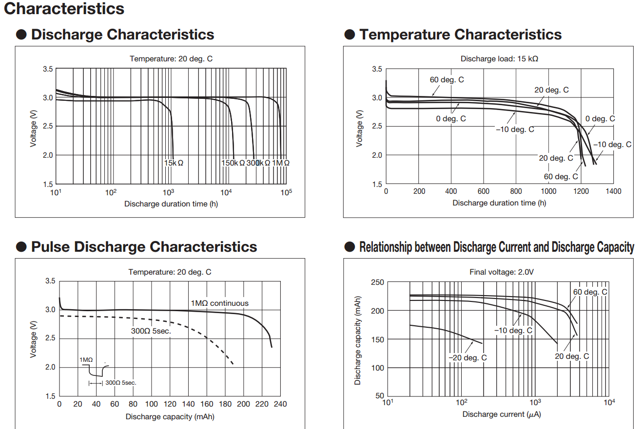
There are app_utils.h information below.

  • @brief Function for converting the input voltage (in milli volts) into percentage of 3.0 Volts.
  • @details The calculation is based on a linearized version of the battery's discharge
  •       curve. 3.0V returns 100% battery level. The limit for power failure is 2.1V and
    
  •       is considered to be the lower boundary.
    
  •       The discharge curve for CR2032 is non-linear. In this model it is split into
    
  •       4 linear sections:
    
  •       - Section 1: 3.0V - 2.9V = 100% - 42% (58% drop on 100 mV)
    
  •       - Section 2: 2.9V - 2.74V = 42% - 18% (24% drop on 160 mV)
    
  •       - Section 3: 2.74V - 2.44V = 18% - 6% (12% drop on 300 mV)
    
  •       - Section 4: 2.44V - 2.1V = 6% - 0% (6% drop on 340 mV)
    
  •       These numbers are by no means accurate. Temperature and
    
  •       load in the actual application is not accounted for!
    
  • @param[in] mvolts The voltage in mV
  • @return Battery level in percent.

I don't understand the above graph look.

How can I split like a source in the app_utils.h?

What are criteria divides?

And can you analyze that graph?

If you analyze, what should I do?

Or is there another way?

Oh.. I use CR2032. I would like to know how to use, even if the other batteries ago.

  • I am not quite sure what you want to do. Do you want to convert the measurement of your battery's voltage to a percentage of the usable capacity left? Something like:

    3V = 100%, 2V = 0% and a function for in between?

    The measurement is no problem. And the conversion neither. Is is never exact.. As the graphics you posted show it is dependent on discharge rate , temperature and so on. For most cases a simple linear function should be enough.

  • Thank you for reply.

    Hi muhkuhns, I don't understand your answer.

    Do you know this function? --> battery_level_in_percent()

    I see only that graph, I don't know how to divide sections like battery_level_in_percent function.

    In this function you are being told, "It has been calculated regardless of the temperature and load."

    But I'd like to know what based on can be divided as follows:

  • if (mvolts> = 3000)

         {

             battery_level = 100;

         }

         else if (mvolts> 2900)

         {

             battery_level = 100 - ((3000 - mvolts) * 58) / 100;

         }

         else if (mvolts> 2740)

         {

             battery_level = 42 - ((2900 - mvolts) * 24) / 160;

         }

         else if (mvolts> 2440)

         {

             battery_level = 18 - ((2740 - mvolts) * 12) / 300;

         }

         else if (mvolts> 2100)

         {

             battery_level = 6 - ((2440 - mvolts) * 6) / 340;

         }

         else

         {

             battery_level = 0;

         }

  • Hi

    The code above attempts to divide the voltage decline of the battery into several linear sections. Yes you are correct, it is a challange to place those linear sections correctly because apparently they are dependent on both temperature and how fast you drain the battery.

    The nRF51 has an internal temperature meter and you could use that to figure out the battery level relative to the temperature.

    Also, most likely you know how fast you drain your battery since you know what application you are running on the device and approximately know the current consumption of the application.

    The battery voltage to battery level can never be accurate, it will always be an assumption since there are several factors in the battery voltage to battery level transfer function. It is also hard because the voltage decline of the battery is rather slow, especially between ~30%-80% battery level. Anyway, from you "pulse discharge characteristics" graph it seems that the discharge is more vertical (and therefore more managable) when the load is high. Therefore I would recommend to measure the battery voltage when the nRF51 is drawing the most current, i.e. during a radio event. This could be achieved with using radio notifications which signal the application just before BLE radio event. There you could start a timer which would trigger ADC start when the radio is active. Use a PPI channel to connect together the timer event and the ADC start task.

    Update 7.6.2015 An example showing timer triggering ADC task through PPI channel is shown here. A radio notification example is shared here.

Related