Hi,
I am designing a board with the nRF52832 and would like to add a chip antenna to the board for BLE.
I am unsure about the necessary matching circuit and although I found a very similar question here, I would like to make sure that I understood it correctly:
Planned chip antenna: 2450AT43F0100
The nRF52832 reference circuit (p. 551) suggests a matching circuit consisting of L1 and C3. The antenna datasheet p.1 also shows a "pi" (or shunt-series-shunt) network in front of the chip antenna. Is it correct to assume that both is needed? That means:
nRF ANT Output -> L1+C3 -> 50 ohm feeding trace -> pi network -> chip antenna
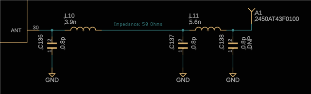
Furthermore, is the length of the feed line important? On page 2 of the datasheet the feed line is 18mm long but this seems to be the dimension on their eval board.
Thank you very much!
Best regards,
Nordix