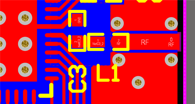
nRF52832 with Chip Antenna

Hi,

I am designing a board with the nRF52832 and would like to add a chip antenna to the board for BLE. 

I am unsure about the necessary matching circuit and although I found a very similar question here, I would like to make sure that I understood it correctly:

Planned chip antenna: 2450AT43F0100 

The nRF52832 reference circuit (p. 551) suggests a matching circuit consisting of L1 and C3. The antenna datasheet p.1 also shows a  "pi" (or shunt-series-shunt) network in front of the chip antenna. Is it correct to assume that both is needed? That means:

nRF ANT Output -> L1+C3 -> 50 ohm feeding trace -> pi network -> chip antenna

Schematic Example

Furthermore, is the length of the feed line important? On page 2 of the datasheet the feed line is 18mm long but this seems to be the dimension on their eval board.

Thank you very much!

Best regards,
Nordix

Parents
  • Hi,

    Both networks are needed, the one in the nRF52832 reference circuit is matching the ANT pin to the 50 Ohm transmission line and is filtering out the harmonic frequency emission.

    Furthermore, is the length of the feed line important?

    The length feed line is not important, we recommend it is kept as short as possible.  The only thing to keep in mind is to not make it 1/4 wavelength, roughly 30mm, as this may cause unwanted effects.


    Best regards,

    Bendik

Reply
  • Hi,

    Both networks are needed, the one in the nRF52832 reference circuit is matching the ANT pin to the 50 Ohm transmission line and is filtering out the harmonic frequency emission.

    Furthermore, is the length of the feed line important?

    The length feed line is not important, we recommend it is kept as short as possible.  The only thing to keep in mind is to not make it 1/4 wavelength, roughly 30mm, as this may cause unwanted effects.


    Best regards,

    Bendik

Children
Related