This discussion has been locked.
You can no longer post new replies to this discussion. If you have a question you can start a new discussion

NCS v2.4.0: low power by example

Dear Support team,

I'm involved in the activity to migrate to NCS a project already developed & successfuly tested with using nRF52 SDK v17.1.0, over the custom board initially designed.

That custom board is based on nRF52832_xxAA, battery powered, equipped with an inertial sensor from STM (MEMS) over SPI0, and a 8Mbit flash memory over SPI1, plus some LEDs and one button. The original .dts file is contained in the folder "<ncs_path>\v2.4.0\zephyr\boards\arm\nrf52dk_nrf52832" successfully overlayed for what concerns the custom I/O mapping. Indeed, everything is working fine without MCUBOOT (I'll add it as a final step when everything will be fixed), until I decided to check the power absorbment from the battery that reported around 150 microAmps in "idle" mode (advertising active and the whole system waiting for events).

As I expect an absorbment from 10 to 20 microAmp, I decided to start from the beginning: the "empty" main as reported below:

int main(void)
{
   while(1)
      NRF_POWER->SYSTEMOFF = 1;

   return 0;
}

This "empty" main reports 30.0 microAmps (NCS) against the 0.30 microAmps reported by the same "empty" main in the APP built with SDK v17.1.0, anyone could tell me whats's possibly wrong ?


PS: "CONFIG_SERIAL=n" has been applied already as many posts seeemed to be resolutive, also in the overlay "&uart0" is stated as "disabled".

PS #2: already included and built some examples from zephyr/samples/bluetooth (only advertising just to remain basic) and I never saw an absorbment less than 100 microAmps, therefore I can't exclude the extension nRF Connect for VSCode, as it's common to all test made so far

Parents
  • Hi,


    Could you try setting the /CSN pins for these sensors to the inactive? 

    If the SPI Flash is enabled, could you try setting it to a suspended state before entering systemoff?

    dev = DEVICE_DT_GET(DT_NODELABEL(my_device));
    pm_device_action_run(dev, PM_DEVICE_ACTION_SUSPEND);


    Kind regards,

    Håkon

  • Dear Hakon,

    thank you for your prompt reply.

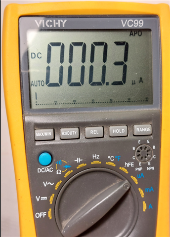
    You got the point, indeed, even if no modules were compiled other than "main.c", there was CONFIG_SPI=y in prj.conf still enabled therefore your doubt about SPI initialized before main() was correct. Now the absorbment is back to 0.3 microAmps as reported from my multimeter (see picture attached).

    Let me take advantage of your availability to ask you a working example of pm_device_action_run() so that I can understand the correct approach to save power when no resource are needed.

    thank you so much for now

    regards, Paolo

  • Hi,


    Are you testing on a nRF52-DK?

    If yes, then you should avoid using the pins that are connected to the debugger UART pins (ie. P0.05 to P0.08) for your SPI communication.

    Here's the overlay that I used:

    &pinctrl {
    	my_spi0_default: my_spi0_default {
    		group1 {
    			psels = <NRF_PSEL(SPIM_SCK, 0, 28)>,
    				<NRF_PSEL(SPIM_MOSI, 0, 29)>,
    				<NRF_PSEL(SPIM_MISO, 0, 30)>;
    		};
    	};
    
    	my_spi0_sleep: my_spi0_sleep {
    		group1 {
    			psels = <NRF_PSEL(SPIM_SCK, 0, 25)>,
    				<NRF_PSEL(SPIM_MOSI, 0, 26)>,
    				<NRF_PSEL(SPIM_MISO, 0, 24)>;
    			low-power-enable;
    		};
    	};
    
    	my_spi1_default: my_spi1_default {
    		group1 {
    			psels = <NRF_PSEL(SPIM_SCK, 0, 23)>,
    				<NRF_PSEL(SPIM_MOSI, 0, 19)>,
    				<NRF_PSEL(SPIM_MISO, 0, 18)>;
    		};
    	};
    
    	my_spi1_sleep: my_spi1_sleep {
    		group1 {
    			psels = <NRF_PSEL(SPIM_SCK, 0, 10)>,
    				<NRF_PSEL(SPIM_MOSI, 0, 11)>,
    				<NRF_PSEL(SPIM_MISO, 0, 3)>;
    			low-power-enable;
    		};
    	};
    };
    
    &spi0 {
    //	compatible = "nordic,nrf-spim";
    	status = "okay";
    	pinctrl-0 = <&my_spi0_default>;
    	pinctrl-1 = <&my_spi0_sleep>;
    	pinctrl-names = "default", "sleep";
    	cs-gpios = <&gpio0 12 GPIO_ACTIVE_LOW>;
    	spi0_cs: spi0_cs@0 {
    		reg = <0>;
    	};
    };
    
    &spi1 {
    //	compatible = "nordic,nrf-spim";
    	status = "okay";
    	pinctrl-0 = <&my_spi1_default>;
    	pinctrl-1 = <&my_spi1_sleep>;
    	pinctrl-names = "default", "sleep";
    	cs-gpios = <&gpio0 22 GPIO_ACTIVE_LOW>;
    	spi1_cs: spi1_cs@0 {
    		reg = <0>;
    	};
    };
    
    &i2c0 {
    	status = "disabled";
    };


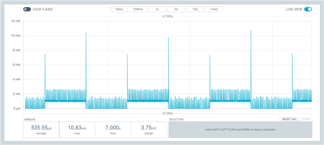
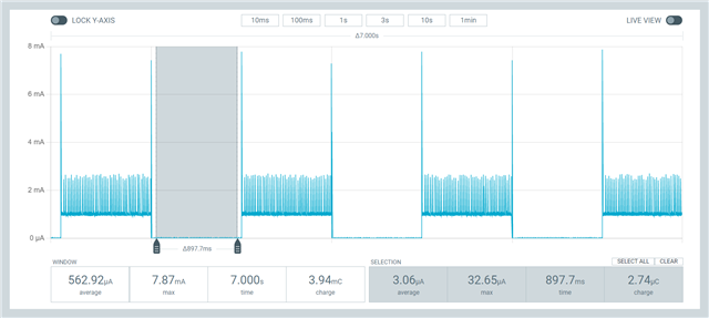
    And here's the current consumption:


    Kind regards,

    Håkon

  • Dear Hakon,

    I'm working on a custom board but I reduced the absorption by removing everything not related to SPI0 from the .dtsi & overlay files...

    I managed to reproduce the issue just re-enabling the section SPI1 configuration in the overlay file.

    Of course it was only a test and I need also SPI1 that on my custom board is unfortunately connected to pins 2,3,6,7 (CS,MISO,MOSI,CLK). Consider that I do not need UART on my project (at the moment), how can solve the issue ?

    Pls find attached the full project in a .zip file8371.blinky.7z

    Pls consider that this is only the first step toward the final approach "Device Runtime Management" in which SPIx resources will be awaken before use them and put them again in sleep mode after use. On this I haven't yet nothing working. Anyway...one thing at a time...

    thank you, Paolo

  • In the meanwhile I restored &uart0 with real pins on the custom board in .dts, still SPI1 when defined pulls up absorption to 30 microAmps even if not used (blinky example). If I removed SPI1from .dts the absorption get back to 3 microAmps.

    Pls find attached .zip project

    blinky2.7z

    thank you, Paolo

  • Hi Paolo,


    Is there anything on your board that can account for the added current consumption?

    If there is, have you tried to isolate the nRF only to see if this lowers the current?


    Depending on the type of ext flash you're using, 30 uA can potentially be the stand-by current consumption of that IC.


    Kind regards,

    Håkon

  • Hi Hakon,

    Yes, there is an external SPI flash but I assume that when all related I/O pins are set to HI-Z it shouldn't be backdriven, anyway just to try I've uncommented the line below for &spi0 and &spi1:

       compatible = "nordic,nrf-spim";
    And magically the extra-current disappeared !!!! How do you explain this?
    thank you, Paolo
    // compatible = "nordic,nrf-spim";
    compatible = "nordic,nrf-spim";

    tag.dts

    /*
     * Copyright (c) 2017 Shawn Nock <[email protected]>
     * Copyright (c) 2017 Linaro Limited
     *
     * SPDX-License-Identifier: Apache-2.0
     */
    
    /dts-v1/;
    #include <nordic/nrf52832_qfaa.dtsi>
    #include "nrf52dk_nrf52832-pinctrl.dtsi"
    
    / {
    	model = "Nordic nRF52 DK NRF52832";
    	compatible = "nordic,nrf52-dk-nrf52832";
    
    	chosen {
    		zephyr,console = &uart0;
    		zephyr,shell-uart = &uart0;
    		zephyr,uart-mcumgr = &uart0;
    		zephyr,bt-mon-uart = &uart0;
    		zephyr,bt-c2h-uart = &uart0;
    		zephyr,sram = &sram0;
    		zephyr,flash = &flash0;
    		zephyr,code-partition = &slot0_partition;
    	};
    
    	/* These aliases are provided for compatibility with samples */
    	aliases {
    		// led0 = &led0;
    		// led1 = &led1;
    		// led2 = &led2;
    		// led3 = &led3;
    		// pwm-led0 = &pwm_led0;
    		// sw0 = &button0;
    		// sw1 = &button1;
    		// sw2 = &button2;
    		// sw3 = &button3;
    		// bootloader-led0 = &led0;
    		// mcuboot-button0 = &button0;
    		// mcuboot-led0 = &led0;
    		watchdog0 = &wdt0;
    	};
    };
    
    &adc {
    	status = "okay";
    };
    
    &gpiote {
    	status = "okay";
    };
    
    &gpio0 {
    	status = "okay";
    };
    
    &uart0 {
    	status = "okay";
    	compatible = "nordic,nrf-uarte";
    	current-speed = <115200>;
    	pinctrl-0 = <&uart0_default>;
    	pinctrl-1 = <&uart0_sleep>;
    	pinctrl-names = "default", "sleep";
    };
    
    &pinctrl {
    	uart0_default: uart0_default {
    		group1 {
    			psels = <NRF_PSEL(UART_TX, 0, 20)>,
    				<NRF_PSEL(UART_RX, 0, 19)>;
    		};
    	};
    
    	uart0_sleep: uart0_sleep {
    		group1 {
    			psels = <NRF_PSEL(UART_TX, 0, 20)>,
    				<NRF_PSEL(UART_RX, 0, 19)>;
    			low-power-enable;
    		};
    	};
    
    	spi0_default: spi0_default {
    		group1 {
    			psels = <NRF_PSEL(SPIM_SCK, 0, 17)>,
    				<NRF_PSEL(SPIM_MOSI, 0, 16)>,
    				<NRF_PSEL(SPIM_MISO, 0, 15)>;
    		};
    	};
    
    	spi0_sleep: spi0_sleep {
    		group1 {
    			psels = <NRF_PSEL(SPIM_SCK, 0, 17)>,
    				<NRF_PSEL(SPIM_MOSI, 0, 16)>,
    				<NRF_PSEL(SPIM_MISO, 0, 15)>;
    			low-power-enable;
    		};
    	};
    
    	spi1_default: spi1_default {
    		group1 {
    			psels = <NRF_PSEL(SPIM_SCK, 0, 7)>,
    				<NRF_PSEL(SPIM_MOSI, 0, 6)>,
    				<NRF_PSEL(SPIM_MISO, 0, 3)>;
    		};
    	};
    
    	spi1_sleep: spi1_sleep {
    		group1 {
    			psels = <NRF_PSEL(SPIM_SCK, 0, 7)>,
    				<NRF_PSEL(SPIM_MOSI, 0, 6)>,
    				<NRF_PSEL(SPIM_MISO, 0, 3)>;
    			low-power-enable;
    		};
    	};
    };
    
    &spi0 {
    	compatible = "nordic,nrf-spim";
    	status = "okay";
    	pinctrl-0 = <&spi0_default>;
    	pinctrl-1 = <&spi0_sleep>;
    	pinctrl-names = "default", "sleep";
    	cs-gpios = <&gpio0 18 GPIO_ACTIVE_LOW>;
    	spi0_cs: spi0_cs@0 {
    		reg = <0>;
    	};
    };
    	
    &spi1 {
    	compatible = "nordic,nrf-spim";
    	status = "okay";
    	pinctrl-0 = <&spi1_default>;
    	pinctrl-1 = <&spi1_sleep>;
    	pinctrl-names = "default", "sleep";
     	cs-gpios = <&gpio0 2 GPIO_ACTIVE_LOW>;
     	spi1_cs: spi1_cs@0 {
     		reg = <0>;
     	};
    };
    
    &flash0 {
    
    	partitions {
    		compatible = "fixed-partitions";
    		#address-cells = <1>;
    		#size-cells = <1>;
    
    		boot_partition: partition@0 {
    			label = "mcuboot";
    			reg = <0x00000000 0xc000>;
    		};
    		slot0_partition: partition@c000 {
    			label = "image-0";
    			reg = <0x0000C000 0x37000>;
    		};
    		slot1_partition: partition@43000 {
    			label = "image-1";
    			reg = <0x00043000 0x37000>;
    		};
    		storage_partition: partition@7a000 {
    			label = "storage";
    			reg = <0x0007a000 0x00006000>;
    		};
    	};
    };
    

Reply
  • Hi Hakon,

    Yes, there is an external SPI flash but I assume that when all related I/O pins are set to HI-Z it shouldn't be backdriven, anyway just to try I've uncommented the line below for &spi0 and &spi1:

       compatible = "nordic,nrf-spim";
    And magically the extra-current disappeared !!!! How do you explain this?
    thank you, Paolo
    // compatible = "nordic,nrf-spim";
    compatible = "nordic,nrf-spim";

    tag.dts

    /*
     * Copyright (c) 2017 Shawn Nock <[email protected]>
     * Copyright (c) 2017 Linaro Limited
     *
     * SPDX-License-Identifier: Apache-2.0
     */
    
    /dts-v1/;
    #include <nordic/nrf52832_qfaa.dtsi>
    #include "nrf52dk_nrf52832-pinctrl.dtsi"
    
    / {
    	model = "Nordic nRF52 DK NRF52832";
    	compatible = "nordic,nrf52-dk-nrf52832";
    
    	chosen {
    		zephyr,console = &uart0;
    		zephyr,shell-uart = &uart0;
    		zephyr,uart-mcumgr = &uart0;
    		zephyr,bt-mon-uart = &uart0;
    		zephyr,bt-c2h-uart = &uart0;
    		zephyr,sram = &sram0;
    		zephyr,flash = &flash0;
    		zephyr,code-partition = &slot0_partition;
    	};
    
    	/* These aliases are provided for compatibility with samples */
    	aliases {
    		// led0 = &led0;
    		// led1 = &led1;
    		// led2 = &led2;
    		// led3 = &led3;
    		// pwm-led0 = &pwm_led0;
    		// sw0 = &button0;
    		// sw1 = &button1;
    		// sw2 = &button2;
    		// sw3 = &button3;
    		// bootloader-led0 = &led0;
    		// mcuboot-button0 = &button0;
    		// mcuboot-led0 = &led0;
    		watchdog0 = &wdt0;
    	};
    };
    
    &adc {
    	status = "okay";
    };
    
    &gpiote {
    	status = "okay";
    };
    
    &gpio0 {
    	status = "okay";
    };
    
    &uart0 {
    	status = "okay";
    	compatible = "nordic,nrf-uarte";
    	current-speed = <115200>;
    	pinctrl-0 = <&uart0_default>;
    	pinctrl-1 = <&uart0_sleep>;
    	pinctrl-names = "default", "sleep";
    };
    
    &pinctrl {
    	uart0_default: uart0_default {
    		group1 {
    			psels = <NRF_PSEL(UART_TX, 0, 20)>,
    				<NRF_PSEL(UART_RX, 0, 19)>;
    		};
    	};
    
    	uart0_sleep: uart0_sleep {
    		group1 {
    			psels = <NRF_PSEL(UART_TX, 0, 20)>,
    				<NRF_PSEL(UART_RX, 0, 19)>;
    			low-power-enable;
    		};
    	};
    
    	spi0_default: spi0_default {
    		group1 {
    			psels = <NRF_PSEL(SPIM_SCK, 0, 17)>,
    				<NRF_PSEL(SPIM_MOSI, 0, 16)>,
    				<NRF_PSEL(SPIM_MISO, 0, 15)>;
    		};
    	};
    
    	spi0_sleep: spi0_sleep {
    		group1 {
    			psels = <NRF_PSEL(SPIM_SCK, 0, 17)>,
    				<NRF_PSEL(SPIM_MOSI, 0, 16)>,
    				<NRF_PSEL(SPIM_MISO, 0, 15)>;
    			low-power-enable;
    		};
    	};
    
    	spi1_default: spi1_default {
    		group1 {
    			psels = <NRF_PSEL(SPIM_SCK, 0, 7)>,
    				<NRF_PSEL(SPIM_MOSI, 0, 6)>,
    				<NRF_PSEL(SPIM_MISO, 0, 3)>;
    		};
    	};
    
    	spi1_sleep: spi1_sleep {
    		group1 {
    			psels = <NRF_PSEL(SPIM_SCK, 0, 7)>,
    				<NRF_PSEL(SPIM_MOSI, 0, 6)>,
    				<NRF_PSEL(SPIM_MISO, 0, 3)>;
    			low-power-enable;
    		};
    	};
    };
    
    &spi0 {
    	compatible = "nordic,nrf-spim";
    	status = "okay";
    	pinctrl-0 = <&spi0_default>;
    	pinctrl-1 = <&spi0_sleep>;
    	pinctrl-names = "default", "sleep";
    	cs-gpios = <&gpio0 18 GPIO_ACTIVE_LOW>;
    	spi0_cs: spi0_cs@0 {
    		reg = <0>;
    	};
    };
    	
    &spi1 {
    	compatible = "nordic,nrf-spim";
    	status = "okay";
    	pinctrl-0 = <&spi1_default>;
    	pinctrl-1 = <&spi1_sleep>;
    	pinctrl-names = "default", "sleep";
     	cs-gpios = <&gpio0 2 GPIO_ACTIVE_LOW>;
     	spi1_cs: spi1_cs@0 {
     		reg = <0>;
     	};
    };
    
    &flash0 {
    
    	partitions {
    		compatible = "fixed-partitions";
    		#address-cells = <1>;
    		#size-cells = <1>;
    
    		boot_partition: partition@0 {
    			label = "mcuboot";
    			reg = <0x00000000 0xc000>;
    		};
    		slot0_partition: partition@c000 {
    			label = "image-0";
    			reg = <0x0000C000 0x37000>;
    		};
    		slot1_partition: partition@43000 {
    			label = "image-1";
    			reg = <0x00043000 0x37000>;
    		};
    		storage_partition: partition@7a000 {
    			label = "storage";
    			reg = <0x0007a000 0x00006000>;
    		};
    	};
    };
    

Children
  • Hi All,

    Trying to make some steps ahead I began to evolve blinky project by initializing some structures aiming to exchange some basic data but unfortunately I got the following error from linker:

    d:/programmi/ncs/toolchains/31f4403e35/opt/zephyr-sdk/arm-zephyr-eabi/bin/../lib/gcc/arm-zephyr-eabi/12.2.0/../../../../arm-zephyr-eabi/bin/ld.bfd.exe: app/libapp.a(main.c.obj): in function `spi_init':
    D:\Project\blinky\src\main.c:74: undefined reference to `__device_dts_ord_78'
    collect2.exe: error: ld returned 1 exit status

    That error arises only when: compatible = "nordic,nrf-spim"; if I replace with: compatible = "nordic,nrf-spi" the error disappears and the build completes successfully.

    Anyone can tell me what's missing ?

    thank you in advance, Paolo

    main.c

    /*
     * Copyright (c) 2016 Intel Corporation
     *
     * SPDX-License-Identifier: Apache-2.0
     */
    
    #include <zephyr/kernel.h>
    #include <zephyr/drivers/gpio.h>
    #include <zephyr/drivers/spi.h>
    
    /* 1000 msec = 1 sec */
    #define SLEEP_TIME_MS   1000
    
    /* The devicetree node identifier for the "led0" alias. */
    #define LED0_NODE DT_NODELABEL(led_red)
    
    /*
     * A build error on this line means your board is unsupported.
     * See the sample documentation for information on how to fix this.
     */
    static const struct gpio_dt_spec led = GPIO_DT_SPEC_GET(LED0_NODE, gpios);


    // MEMS
    #define MEMS_SPI_NODE			DT_NODELABEL(spi0)
    static const struct device 	*mems_spi_dev = DEVICE_DT_GET(MEMS_SPI_NODE);
    
    #define MEMS_SPI_CS_NODE		DT_NODELABEL(spi0_cs)
    static const struct spi_cs_control mems_spi_cs_ctrl = {
    	.gpio = SPI_CS_GPIOS_DT_SPEC_GET(MEMS_SPI_CS_NODE),
    	.delay = 2
    };
    
    static const struct spi_config mems_spi_cfg = {
    	.frequency = 8000000,	// 8MHZ
    	.operation = SPI_WORD_SET(8),
    	.cs = &mems_spi_cs_ctrl
    };
    
    #define	SPI_BUF_SIZE	256
    static uint8_t tx_buf[SPI_BUF_SIZE];
    static uint8_t rx_buf[SPI_BUF_SIZE];
    
    static struct spi_buf tx_spi_bufs[] = {
    	{
    		.buf = tx_buf
    	}
    };
    
    static struct spi_buf rx_spi_bufs[] = {
    	{
    		.buf = rx_buf
    	}
    };
    
    static const struct spi_buf_set spi_tx_buf_set = {
    	.buffers = tx_spi_bufs,
    	.count = 1
    };
    
    static const struct spi_buf_set spi_rx_buf_set = {
    	.buffers = rx_spi_bufs,
    	.count = 1
    };
    
    
    int spi_init(void)
    {
    	if (!device_is_ready(mems_spi_dev))
    		return 1;
    
    	return 0;	// OK
    }
    
    
    int main(void)
    {
    	if (!gpio_is_ready_dt(&led))
    	{
    		return 0;
    	}
    
    	int ret = gpio_pin_configure_dt(&led, GPIO_OUTPUT_ACTIVE);
    	if (ret < 0)
    		return 0;
    
    	spi_init();
    
    	while (1) 
    	{
    		ret = gpio_pin_toggle_dt(&led);
    		if (ret < 0)
    			return 0;
    		
    		k_msleep(SLEEP_TIME_MS);
    	}
    	
    	return 0;
    }
    

    board.dts

    /*
     * Copyright (c) 2017 Shawn Nock <[email protected]>
     * Copyright (c) 2017 Linaro Limited
     *
     * SPDX-License-Identifier: Apache-2.0
     */
    
    /dts-v1/;
    #include <nordic/nrf52832_qfaa.dtsi>
    #include "nrf52dk_nrf52832-pinctrl.dtsi"
    
    / {
    	model = "Nordic nRF52 DK NRF52832";
    	compatible = "nordic,nrf52-dk-nrf52832";
    
    	chosen {
    		zephyr,console = &uart0;
    		zephyr,shell-uart = &uart0;
    		zephyr,uart-mcumgr = &uart0;
    		zephyr,bt-mon-uart = &uart0;
    		zephyr,bt-c2h-uart = &uart0;
    		zephyr,sram = &sram0;
    		zephyr,flash = &flash0;
    		zephyr,code-partition = &slot0_partition;
    	};
    
    	/* These aliases are provided for compatibility with samples */
    	aliases {
    		// led0 = &led0;
    		// led1 = &led1;
    		// led2 = &led2;
    		// led3 = &led3;
    		// pwm-led0 = &pwm_led0;
    		// sw0 = &button0;
    		// sw1 = &button1;
    		// sw2 = &button2;
    		// sw3 = &button3;
    		// bootloader-led0 = &led0;
    		// mcuboot-button0 = &button0;
    		// mcuboot-led0 = &led0;
    		watchdog0 = &wdt0;
    	};
    };
    
    &adc {
    	status = "okay";
    };
    
    &gpiote {
    	status = "okay";
    };
    
    &gpio0 {
    	status = "okay";
    };
    
    &pinctrl {
    	uart0_default: uart0_default {
    		group1 {
    			psels = <NRF_PSEL(UART_TX, 0, 20)>,
    				<NRF_PSEL(UART_RX, 0, 19)>;
    		};
    	};
    
    	uart0_sleep: uart0_sleep {
    		group1 {
    			psels = <NRF_PSEL(UART_TX, 0, 20)>,
    				<NRF_PSEL(UART_RX, 0, 19)>;
    			low-power-enable;
    		};
    	};
    
    	spi0_default: spi0_default {
    		group1 {
    			psels = <NRF_PSEL(SPIM_SCK, 0, 17)>,
    				<NRF_PSEL(SPIM_MOSI, 0, 16)>,
    				<NRF_PSEL(SPIM_MISO, 0, 15)>;
    		};
    	};
    
    	spi0_sleep: spi0_sleep {
    		group1 {
    			psels = <NRF_PSEL(SPIM_SCK, 0, 17)>,
    				<NRF_PSEL(SPIM_MOSI, 0, 16)>,
    				<NRF_PSEL(SPIM_MISO, 0, 15)>;
    			low-power-enable;
    		};
    	};
    
    	spi1_default: spi1_default {
    		group1 {
    			psels = <NRF_PSEL(SPIM_SCK, 0, 7)>,
    				<NRF_PSEL(SPIM_MOSI, 0, 6)>,
    				<NRF_PSEL(SPIM_MISO, 0, 3)>;
    		};
    	};
    
    	spi1_sleep: spi1_sleep {
    		group1 {
    			psels = <NRF_PSEL(SPIM_SCK, 0, 7)>,
    				<NRF_PSEL(SPIM_MOSI, 0, 6)>,
    				<NRF_PSEL(SPIM_MISO, 0, 3)>;
    			low-power-enable;
    		};
    	};
    };
    
    &uart0 {
    	status = "okay";
    	compatible = "nordic,nrf-uarte";
    	current-speed = <115200>;
    	pinctrl-0 = <&uart0_default>;
    	pinctrl-1 = <&uart0_sleep>;
    	pinctrl-names = "default", "sleep";
    };
    
    &spi0 {
    	compatible = "nordic,nrf-spim";
    	status = "okay";
    	pinctrl-0 = <&spi0_default>;
    	pinctrl-1 = <&spi0_sleep>;
    	pinctrl-names = "default", "sleep";
    	cs-gpios = <&gpio0 18 GPIO_ACTIVE_LOW>;
    	spi0_cs: spi0_cs@0 {
    		reg = <0>;
    	};
    };
    	
    &spi1 {
    	compatible = "nordic,nrf-spim";
    	status = "okay";
    	pinctrl-0 = <&spi1_default>;
    	pinctrl-1 = <&spi1_sleep>;
    	pinctrl-names = "default", "sleep";
     	cs-gpios = <&gpio0 2 GPIO_ACTIVE_LOW>;
     	spi1_cs: spi1_cs@0 {
     		reg = <0>;
     	};
    };
    
    &flash0 {
    
    	partitions {
    		compatible = "fixed-partitions";
    		#address-cells = <1>;
    		#size-cells = <1>;
    
    		boot_partition: partition@0 {
    			label = "mcuboot";
    			reg = <0x00000000 0xc000>;
    		};
    		slot0_partition: partition@c000 {
    			label = "image-0";
    			reg = <0x0000C000 0x37000>;
    		};
    		slot1_partition: partition@43000 {
    			label = "image-1";
    			reg = <0x00043000 0x37000>;
    		};
    		storage_partition: partition@7a000 {
    			label = "storage";
    			reg = <0x0007a000 0x00006000>;
    		};
    	};
    };
    

    board.overlay

    / {
    	outputs {
    		compatible = "gpio-leds";
    		led_red: led_red {
    			gpios = <&gpio0 24 GPIO_ACTIVE_LOW>;
    		};
    	};
    };
    

    prj.conf

    CONFIG_GPIO=y
    CONFIG_SPI=y
    

  • Hi,


    Try deleting your build-folder for each time that you change the "compatible" line in the overlay file. 

    pzuck said:
    I assume that when all related I/O pins are set to HI-Z it shouldn't be backdriven, anyway just to try I've uncommented the line below for &spi0 and &spi1:

    You have to set the CSN inactive to avoid added consumption from any external IC. If it floats, it can draw excessive current.


    Kind regards,

    Håkon

  • Hi,

    The error persists even if I delete "build" folder. Any other hints ?

    As I'm a newbie in Zephyr it would be more effective to figure out the difference between spi & spim in the compatible item...

    regard, Paolo

  • Hi Hakon,

    Pls confirm if you managed to build without errors, I'm stuck on this point since long time...

    thank you, Paolo

  • Hi Paolo,


    Sorry for the late reply.

    Due to this errata on nRF52832: https://infocenter.nordicsemi.com/topic/errata_nRF52832_Rev3/ERR/nRF52832/Rev3/latest/anomaly_832_58.html#anomaly_832_58

    You must select the configuration: CONFIG_SOC_NRF52832_ALLOW_SPIM_DESPITE_PAN_58=y

    You might also need to set: CONFIG_NRFX_PPI=y


    Please note that this restriction should only be applied if you are certain that you will not trigger the above mentioned anomaly.

    This can also explain why you're not seeing a higher current consumption when selecting "nordic,nrf-spim"; as the above kconfig was blocking you from enabling the SPIx instances.


    Even with all of these set at my end (regardless of nrf,spi or nrf,spim used), I still see < 10 uA sleep with your project.

    You need to check if the additional current goes into your external flash.


    Kind regards,

    Håkon

Related