Error when trying to use the PDM interface

Hi

I am trying to collect data from a PDM microphone with the nRF5340DK and using the nRF Connect SDK. I am loosely following the example posted here, but without the SD-card part.

The code in my main file looks like this:

#include <zephyr/kernel.h>
#include <zephyr/drivers/i2c.h>
#include <zephyr/logging/log.h>
#include <nrfx_pdm.h>

#define _pin_clk 18
#define _pin_din 16
static const int size = 4096;
bool flag = 0;
bool WriteFlag = 0;
int16_t buff1[4096];
int16_t buff2[4096];

LOG_MODULE_REGISTER(Main);

static void drv_pdm_hand(const nrfx_pdm_evt_t *evt){
    if((*evt).buffer_requested){
        nrfx_err_t error;
        if(!flag){
            error = nrfx_pdm_buffer_set(&buff1[0], size);
            flag = 1;
            WriteFlag = 1;
        }
        else{
            error = nrfx_pdm_buffer_set(&buff2[0], size);
            flag = 0;
            WriteFlag = 1;
        }
    }
}

int main(void)
{

    nrfx_err_t error;
    nrfx_pdm_config_t config1 = NRFX_PDM_DEFAULT_CONFIG(_pin_clk, _pin_din);

    error = nrfx_pdm_init(&config1, &drv_pdm_hand);


    error = nrfx_pdm_start();
    k_msleep(1000);
    error = nrfx_pdm_stop();
    LOG_INF("DONE");

    return 0;
}

And my config file looks like this:

CONFIG_LOG=y
CONFIG_NRFX_PDM=y

When I run it like this, I get the error:
[00:00:00.252,227] <err> os: >>> ZEPHYR FATAL ERROR 1: Unhandled interrupt on CPU 0
[00:00:00.252,288] <err> os: Current thread: 0x20008738 (main)
[00:00:00.277,313] <err> fatal_error: Resetting system

I then included:

bool clear = nrfx_pdm_enable_check();
    if(clear){
        LOG_INF("The PDM interface is enabled");
    }
    else{
        LOG_INF("The PDM interface is disabled");
    }

From here I always get that the PDM interface is disabled. So I suspect that this is the problem. How do i go about enabling the PDM interface?

Parents Reply
  • I do not have an overlay file. Is that required for this case? I got the pin numbers from the file "C:\ncs\v2.4.0\zephyr\boards\arm\nrf5340dk_nrf5340\nrf5340_cpuapp_common.dts", I thought that might be all that was necessary. I use pin p1.14 for _pin_clk and p1.12 for _pin_din. That should correspond to 18 and 16 respectively.

    Further, what do you mean by "compiled DTS", where do I find that?

    When using the logic analyzer, I have both measured with the mic connected and directly at the board pin(p1.14), but no clock signal is detected either way. So the problem seems to be on the board. 

Children
  • Hello,

    Device Tree Structure information is represented in .DTS files. Zephyr.DTS file is the compiled output file that uses board.dts (specific board information) and board.overlay (user specific overlay files) along with bindings information. The <devicetree.h> header file provides the mechanism to access device nodes from the DTS. This describes the said procedure used in zephyr.

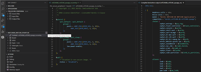
    When ever you want/need to configure your hardware, you do it using the overlay files. An example of overlay file, how to see the compiled DTS, and the zephyr compiled DTS are shown in example project below. 

    Espen said:
    I use pin p1.14 for _pin_clk and p1.12 for _pin_din. That should correspond to 18 and 16 respectively.

    I think you got it wrong. The Arduino header (analog and digital pins) are connected to the gpio0 and gpio1 pins on the DK.

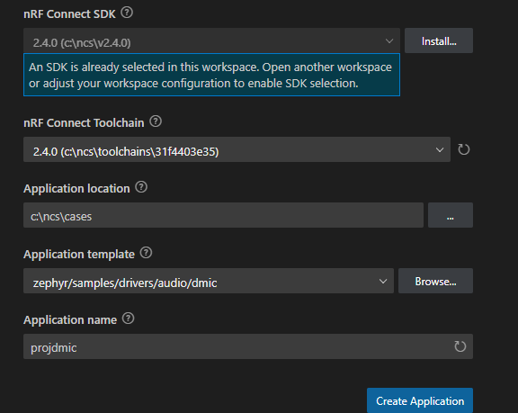
    I suggest you to start looking at DMIC project

    Then compile it for nrf5340dk_nrf5340_cpuapp.

    Have a look at /boards/nrf5340dk_nrf5340_cpuapp.overlay file

    and also at the compiled DTS.

    You would see that the PDM is configured as below

    Clock Port0 pin25

    Datain Port0 pin26

    (you could definitely change the pins and other configurations, but make sure there are no conflicts, and all the requirements are met etc.)

    Hope this sample is related to your needs and would be helpful.

    Regards,

    Naeem

  • Thank you so much for the answer. I have tried it and it runs without error. However I am not sure if the PDM mic is working since the program runs the same if the mic is connected or not. Is there an easy way to test this? For example taking a look at the data stored in an easy way?

    Edit: I manged to measure the signal with a logic analyzer and it works! I will now try it with my program and see if it works

Related