Hi
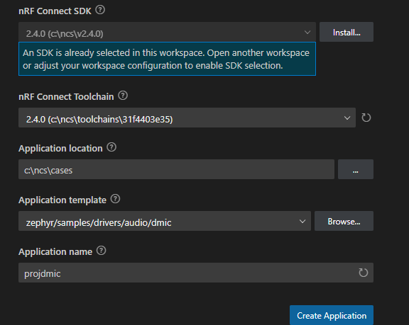
I am trying to collect data from a PDM microphone with the nRF5340DK and using the nRF Connect SDK. I am loosely following the example posted here, but without the SD-card part.
The code in my main file looks like this:
#include <zephyr/kernel.h>
#include <zephyr/drivers/i2c.h>
#include <zephyr/logging/log.h>
#include <nrfx_pdm.h>
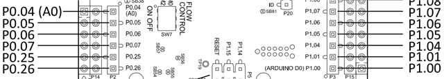
#define _pin_clk 18
#define _pin_din 16
static const int size = 4096;
bool flag = 0;
bool WriteFlag = 0;
int16_t buff1[4096];
int16_t buff2[4096];
LOG_MODULE_REGISTER(Main);
static void drv_pdm_hand(const nrfx_pdm_evt_t *evt){
if((*evt).buffer_requested){
nrfx_err_t error;
if(!flag){
error = nrfx_pdm_buffer_set(&buff1[0], size);
flag = 1;
WriteFlag = 1;
}
else{
error = nrfx_pdm_buffer_set(&buff2[0], size);
flag = 0;
WriteFlag = 1;
}
}
}
int main(void)
{
nrfx_err_t error;
nrfx_pdm_config_t config1 = NRFX_PDM_DEFAULT_CONFIG(_pin_clk, _pin_din);
error = nrfx_pdm_init(&config1, &drv_pdm_hand);
error = nrfx_pdm_start();
k_msleep(1000);
error = nrfx_pdm_stop();
LOG_INF("DONE");
return 0;
}
And my config file looks like this:
CONFIG_LOG=y
CONFIG_NRFX_PDM=y
When I run it like this, I get the error:
[00:00:00.252,227] <err> os: >>> ZEPHYR FATAL ERROR 1: Unhandled interrupt on CPU 0
[00:00:00.252,288] <err> os: Current thread: 0x20008738 (main)
[00:00:00.277,313] <err> fatal_error: Resetting system
I then included:
bool clear = nrfx_pdm_enable_check();
if(clear){
LOG_INF("The PDM interface is enabled");
}
else{
LOG_INF("The PDM interface is disabled");
}
From here I always get that the PDM interface is disabled. So I suspect that this is the problem. How do i go about enabling the PDM interface?