About 27% of GPIOTE events were missed

Hi,

I use NRF52833 with nRF5 SDK 17.1.0 and reference examples/ble_peripheral/ble_app_uart/ for my development.

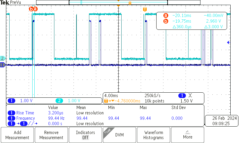
I am using the GPIOTE interrupt for ADS1292R DRDY pin. The DRDY pin will be low in frequency 250 Hz.

My setup for the GPIOTE interrupt is:

static void gpiote_init(void)
{
    ret_code_t err_code;

    err_code = nrf_drv_gpiote_init();
    APP_ERROR_CHECK(err_code);

    nrf_drv_gpiote_in_config_t in_config = GPIOTE_CONFIG_IN_SENSE_HITOLO(true);
    in_config.pull = NRF_GPIO_PIN_PULLUP;

    err_code = nrf_drv_gpiote_in_init(ADS1292_DRDY_IN_PIN, &in_config, ADS1292R_drdyHandler);
    APP_ERROR_CHECK(err_code);

    nrf_drv_gpiote_in_event_enable(ADS1292_DRDY_IN_PIN, true);
}

However, I found bout 27% of GPIOTE events were missed.

Anyone can help. Thanks!

Best Regards,

Terry

Parents Reply Children
  • Following  's example, you can check the mAfeSampleDataReady status in your main loop, and initiate the reading of data from there. This way, you will not be blocking your interrupthandler by doing this in the interrupt itself. 

    Best regards,

    Edvin

  • As Edvin suggests, read in main loop; keep in mind the main sleep loop is woken as a result of the ADS interrupt, so just check the flag. Perhaps add some protection for missed interrupt or ADS1292 streaming fail, since clearly at 250 samples/sec there should be an interrupt every 4mSec; if nothing for (say) 15mSes or whatever longest blocking interrupt such as flash writes takes then attempt to fix:

            // Test for interrupt signal from active-low /DRDY signal
            if (!mAfeSampleDataReady)
            {
                // Not ready: check for missed 4mSec DRDY interrupt, perhaps due to hardware race hazard
                if (TimeSinceLastPacket > ECG_PACKETS_CHECK_TIME)
                {
                    // Looks suspicious, check if the pin signal indicates data ready
                    if (nrf_gpio_pin_read(ADS_DRDY_PIN) == 0)
                    {
                        // Set sample pending signal, as it should have been set
                        mAfeSampleDataReady = true;
                        // Update error log
                        mAfeLateDrdyCount++;
                    }
                    else
                    {
                        // Looks like AFE has ceased 4mSec streaming, try to recover it
                        UnInitAfeInterface();
                        // Update error log
                        mAfeRestartCount++;
                    }
                    // Flag a fault, will be indicated by red led
                    mAfeHasFault = true;
                }
                return;
            }
            else
            {
                // Clear sample pending signal
                mAfeSampleDataReady = false;
                // Clear fault, fault is indicated by red led
                mAfeHasFault = false;
                // Data is ready, read spi
                AdsReadData(mAfeSpiBuffer, ADS1292_SPI_READ_DATA_LENGTH);
                ++AdsConvCounter;
           }

  • Tips on ADS1292 - in case you have not used this ADS1292 AFE before, there are a few issues - which can waste a lot of time - to be aware of.

    The BLE communications packet timing is accurate to the spec of the 32kHz crystal (perhaps +-20ppm) with some extra drift, but let's say below 40ppm. However within a packet the ECG readings are sampled based on the ADS1292 RC AFE oscillator, which is +-0.5% at 25 degrees and +-1.5% -40 to +85 degrees. When reporting an event or correlating a heartbeat with (say) an externally observed fall reported separately this becomes a major headache as the AFE time is way off actual time and so it is hard to find the heartbeats which match the fall or other external event without correlating packet time to AFE time.
    Using an external clock provides better accuracy for the AFE; switch off the AFE internal oscillator and instead use a crystal-derived clock (PWM) to drive the AFE, which largely removes that AFE sampling uncertainty. The downside of enabling this external clock is battery life, since both PWM and 32MHz crystal are enabled; the alternative is a MEMs oscillator, typically 2.048MHz, which can be lower power. The upside is faster SPI transfers:

    // Sending Multi-Byte Commands
    // The ADS1291, ADS1292, and ADS1292R serial interface decodes commands in bytes and requires 4 tCLK cycles
    // to decode and execute. Therefore, when sending multi-byte commands, a 4 tCLK period must separate the end of
    // one byte (or opcode) and the next.
    // Assume CLK is 512 kHz, then tSDECODE (4 tCLK) is 7.8125 us. When SCLK is 16 MHz, one byte can be
    // transferred in 500 ns. This byte-transfer time does not meet the tSDECODE specification; therefore, a delay must be
    // inserted so the end of the second byte arrives 7.3125 us later. If SCLK is 1 MHz, one byte is transferred in 8 us.
    // Because this transfer time exceeds the tSDECODE specification, the processor can send subsequent bytes without
    // delay. In this later scenario, the serial port can be programmed to move from single-byte transfer per cycle to
    // multiple bytes.

        // if using internal ADS1292 RC oscillator ensure less than 4 clk cycles
        spi_config.frequency = NRF_DRV_SPI_FREQ_500K;

    If ADS1292 GPIO pins are configured as inputs, these pins must be externally driven (do not float). The GPIO pins are set as inputs after power-on or after a reset. The pins should be shorted to DGND with a series resistor or direct connection if not used; I program them as active low outputs. Leaving them as floating inputs can cause feedthrough current consumption, usually not observed until there are 1,000 devices in the field.

Related