Noise on PCB during 2.4GHz RF transmission

Hello friends, 

I am using nrf52840-CKAA for my customize PCB. 

I am facing the noise during RF transmission on my ADC. The peak noise happen when I send a packet of data via RF antenna. 

Power_Tx = 4dBm


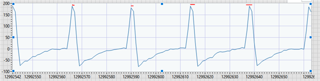
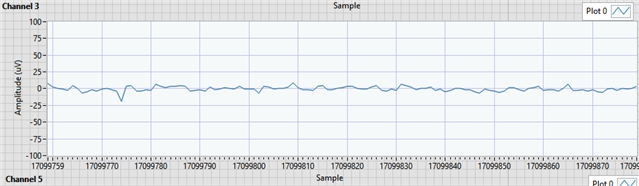
When I decrease the Tx Power to -12dBm, the peak noise was gone.

I wonder that MCU takes a lot of power during RF transmission so it affect to the stability of power line. 

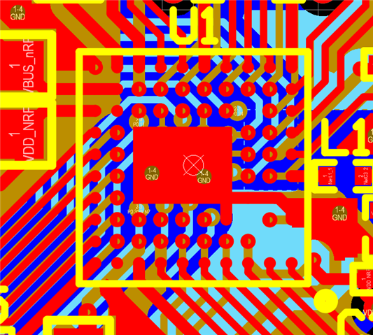
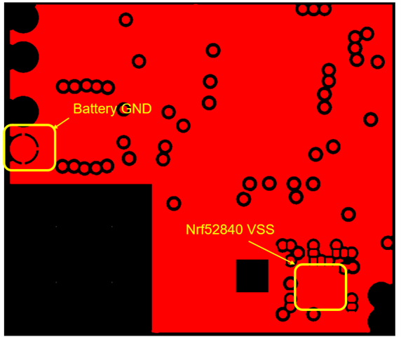
In nrf52840-CKAA, currently I tie all VSS pin together instead of tie each of them directly to the GND plane. Is it the problem? 

I appreciate all your suggestions. 

Minhduc

Parents Reply Children
  • I would just common the ADC VDD pins and drive from a single Ideal Diode; it is not clear which VDD pin supplies which subsystem within the ADC die, often one is used for io and others for analogue but it doesn't matter here I don't think. Capacitor should be (say) 47uF 6.3V or (better) 10V or 16V rating. Normally connect EN to Vdd (ie nRF VDD) or leave floating (EN has internal pull-up). Note "It is not necessary (or recommended) to use separate “analog” and “digital” power lines."

    VSTIM would perhaps be treated separately if also coming from nRF VDD.

  • It was very clear. I don't have experience using ideal diode for this purpose. Can you please recommend which one is better for my case? Ideal diode or separate LDO? 

    Appreciate your help. 

  • If using a battery with plenty of capacity, such as a rechargeable battery or AA cells, or external supply such as USB, then the average VDD voltage probably stays high enough for 3.3 volt operation and so use the ideal diode (small, cheap, low voltage drop 30mV). If using (say) CR2032 or CR2540 coin cells where the voltage will drop over time to (say) 2.7 volts, then a buck-boost regulator to supply the ADC with 3.3 volts becomes mandatory. If using such a buck-boost regulator to maintain 3.3 volts for the ADC, choose one which will hold the voltage output even when the input voltage sags or drops sharply. Something like a TPS63000; there are lots of options but I use this one. TPS63000 in which case this replaces the Ideal Diode.

    How are you handling the 32-bit SPI transfer /CS requirement other than millions of short transfers? "The CS line must be pulsed high between every 32-bit data transfer.; ie. /CS stays high for 154 ns between words"

  • Thank you for sharing. 

    My SPI is ok. It’s around 1.5us CS pulse high between each 32-bit SPI command.

  • I was thinking more of high transfer rate with long DMA transfers to get predictably even sampling, given that the radio requires interrupt priority short transfers do not work well and lead to unpredictable sampling unless scheduled away from radio activity. Something like the STM32U535xx; For the nRF5x PWM spoofing of SCK, MOSI and /CS works in conjunction with using SPIS instead of SPIM to receive the data but the frequency is on the low side. Spoofing of SCK, MOSI and /CS with PPI-linked timers is also an option, but increases power due to the significant number of peripherals running and synchronising the timers requires care. What data rate do you achieve?

Related