UART not powering down Zephyr

Hi,

I am using nRF Connect SDK V2.3.0. How can I power down the UART?

I am using the Interrupt-driven UART API, interrupt driven on RX and polling on TX. I have disabled the console on the dtb and prj.conf. I am using both UARTs in my application to talk to external peripherals (so I do not need logging nor the console on any of the UARTs). My application is a very low power application, micro amps matter here.

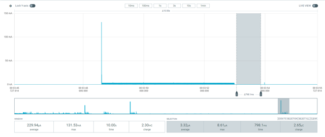
When I do not use the UART my power consumption is nice and low. As soon as I use the UART my power consumption jumps by 1.3mA, not good to say the least. I have tried to use the power manager "pm_device_action_run(uart, PM_DEVICE_ACTION_SUSPEND)", but my power consumption does not drop. I know it is the UART and not something else on my board, because as soon I issue the forbidden register writes, the power consumption drops down to micro amps again:

*(volatile uint32_t *)0x40002FFC = 0;   // Power down UARTE0
I did look at the NRFX UARTE drivers also and they are no good, I cannot know the size of the expected packet, nor drop packets due to a timeout.
.

My question is how can I power down the UART when I am not using it (simular to uninitializing it in the old nRF52 SDK) and then powering it up again when I need it? So technically I want a way to uninitialse the UARTs and re-initialise them again when I need them to save as much power as possible.

Thank you in advance for the assistance. Hope to hear from someone soon.

Kind Regards

Julian

  • Hello Julian,

    Perhaps you can check out the sample found in ncs\nrf\samples\peripheral\lpuart

    The documentation for this sample is found here:

    https://developer.nordicsemi.com/nRF_Connect_SDK/doc/latest/nrf/samples/peripheral/lpuart/README.html

    What I don't understand is that the UART is drawing power even after you power it off. Perhaps you have several uart instances running? Or perhaps the reason are gpios that are left on. Try reverting these to the standard "disconnected input":

    https://infocenter.nordicsemi.com/topic/ps_nrf52840/gpio.html?cp=5_0_0_5_8_1_9#register.PIN_CNF-0-31

    with the value 0x00000002

    Best regards,

    Edvin

  • Hi Edvin,

    Thanks for the feedback. Sorry for my terribly slow response. I did confirm the uart pins are all NRF_P0->PIN_CNF[xx]: 0x00000002 (for uart0 and uart1). So unfortunately it is not that.

    Kind Regards

    Julian

  • Hello Julian,

    JulianWilmot said:
    Sorry for my terribly slow response

    No worries Slight smile

    Is it possible to upload the application that you are currently using (or at least something that reproduces what you are seeing) so that I can have a look and poke around?

    I know it is the UART and not something else on my board, because as soon I issue the forbidden register writes, the power consumption drops down to micro amps again

    I agree that this suggests that there is something related to the UART.

    Best regards,

    Edvin

  • Hi Edvin,

    Hope you are doing well. Certainly, I uploaded a project that reproduces what I am seeing (it is not my actual project source, but just a mockup to test with).

    I did make some progress on this and got some new findings. Just a little bit of context for you. I use two uarts in my application UART0 (RS232 modem) and UART1 (RS485 device). When I have a modem simulator plugged into the RS232 port (UART0) and write an AT command to the modem and the modem responds and I then put both uarts into power down mode then it works as expected. It draws about 100uA. But when I just open a regular serial terminal (which does not respond back) then the device does not power down properly and the current draw is close to 1mA. When on the same setup I reply quickly back once I transmit the AT command over the serial terminal then the current draw is low again. So it seems I have to receive data first on UART0 before I can power down properly.

    Any ideas why I have to receive data first before sleeping, and why only on UART0 and not UART1? Also if I do not send/receive data and just put both UARTs into power down mode after the UART's are ready then it does not work either. 

    Kind Regards

    Julian

    echo_example.zip

  • Hello Julian,

    I tested your application on a DK (slightly modified to have the buttons required to compile:

    #error "Unsupported board: gpspwren devicetree alias is not defined"

    And running the application using the PPK 2, I see this:

    (I added a couple of more delay with some logging, so the timing may be different from what you are seeing)

    However, as you can see, when the grey marked area has a current consumption of 3.32µA, so I don't think I am seeing what you are seeing. 

    Did you test your application on an nRF52840DK? Do you see the same issue there? If you do see the same issue, can you please zip that modified application and upload that as well?

    Best regards,

    Edvin

Related