Good Day.
I'm trying to run the "npm1300_fuel_gauge" example on a custom board (nRF52840), but I'm getting errors that I don't know how to fix.
The first thing I did was to get the PMIC configuration overlay file (config.overlay) through nPM PowerUP. Then I transferred the code from config.overlay to the custom board device tree file (custom_board_nrf52840.dts). I plan to connect the PMIC via I2C1.
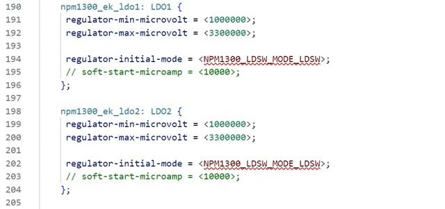
custom_board_nrf52840.dts -->
custom_board_nrf52840-pinctrl.dtsi -->
The following errors occur in the .dts file (see screenshot).
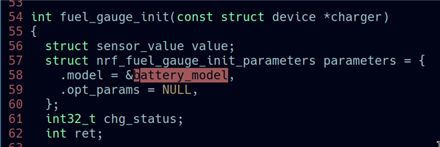
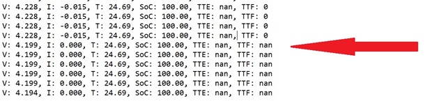
I know that these values should be taken from the "fuel_gauge.h" file, but that doesn't happen for some reason.
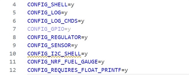
I see an error in the prj.conf file too (see screenshot).
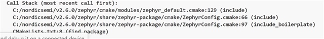
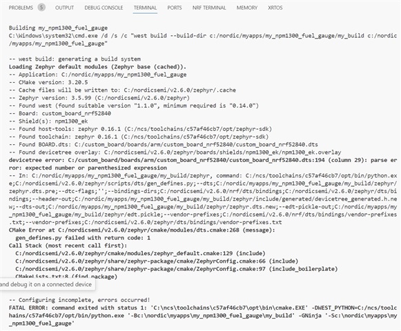
When building the project, I see the following information -->
I have not changed the CMakeLists.txt files.
Can you please tell me where I am making a mistake when transferring this example to my custom board?
Thank you.