Jitter when routing LFCLK on GPIO

Hi

I tried to route the LFCLK (32kHz LFXO) on a GPIO similar to the method that has been described here:

 How to output 32768Hz external crystal LFCLK at a GPIO pin? 

When I run the code on the nRF52832 everything works fine, i.e. I get the proper 16384 Hz signal without jitter.

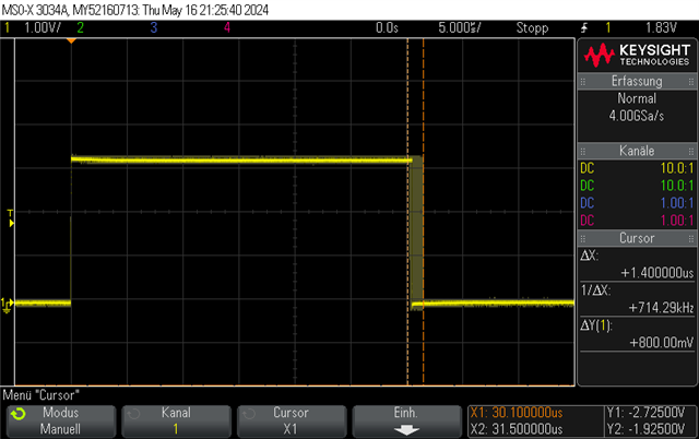
But when I run the same code on the nRF52833, I get a signal that jitters with ~1.4us which leads to a frequency between 15873 and 16612 Hz.

  • In both cases, the external LFXO is running.
  • It doesn't matter if the SoftDevice is running.
  • It seems that the issue only occurs when the application toggles additionally other GPIO(s).

Do you have an explanation for this behavior? Why does it only occur on the nRF52833?

Many thanks in advance.

Best regards, Remo

Parents
  • I tested this code on the nRF52833DK and get a jitter of less than 1nSec with 32kHz crystal enabled:

    // Testing on nRF52833DK
    #define RTC_TEST_PIN    14
    void Test32kHzCrystal(void)
    {
       // measure the frequency of the 32.768kHz crystal - will show as 16.384kHz, 17.484kHz RC typ or 6.7% error
       // 20ppm is +-0.655Hz in 32768Hz
       NRF_RTC_Type *pTickRTC = NRF_RTC2;
       // Select 32kHz clock source
       NRF_CLOCK->LFCLKSRC = CLOCK_LFCLKSRC_SRC_Xtal << CLOCK_LFCLKSRC_SRC_Pos;
       NRF_CLOCK->EVENTS_LFCLKSTARTED = 0;
       // Start 32kHz clock
       NRF_CLOCK->TASKS_LFCLKSTART = 1;
       while (NRF_CLOCK->EVENTS_LFCLKSTARTED == 0) ;
       // Clear started event otherwise won't sleep
       NRF_CLOCK->EVENTS_LFCLKSTARTED = 0;
       NRF_P0->OUTCLR = (1 << RTC_TEST_PIN);
       // Configuration              Direction                Input                          Pullup                 Drive Level        Sense Level
       // =========================  =======================  =============================  =====================  =================  ====================
       nrf_gpio_cfg(RTC_TEST_PIN,    NRF_GPIO_PIN_DIR_OUTPUT, NRF_GPIO_PIN_INPUT_DISCONNECT, NRF_GPIO_PIN_NOPULL,   NRF_GPIO_PIN_H0H1, NRF_GPIO_PIN_NOSENSE);
       // Select tick: 12 bit prescaler for COUNTER frequency (32768/(PRESCALER+1)). Must be written when RTC is stopped
       pTickRTC->PRESCALER = 0;
       // Enable EVENTS_TICK generation
       pTickRTC->EVTENSET = RTC_EVTENSET_TICK_Msk;
       // Start RTC
       pTickRTC->TASKS_START = 1;
       // Configure GPIOTE to control output pin
       NRF_GPIOTE->CONFIG[0] = GPIOTE_CONFIG_MODE_Task << GPIOTE_CONFIG_MODE_Pos | GPIOTE_CONFIG_POLARITY_Toggle << GPIOTE_CONFIG_POLARITY_Pos | RTC_TEST_PIN << GPIOTE_CONFIG_PSEL_Pos;
       // Connect TICK event of the RTC to the output pin using PPI and GPIOTE, toggle so 32768/2=16384Hz expected
       NRF_PPI->CH[0].EEP = (uint32_t)&pTickRTC->EVENTS_TICK;
       NRF_PPI->CH[0].TEP = (uint32_t)&NRF_GPIOTE->TASKS_OUT[0];
       NRF_PPI->CHEN = PPI_CHEN_CH0_Msk;
       while (1)
       {
            __SEV(); __WFE(); __WFE();
       }
    }

  • Thanks for your answer. We could verify that the jitter only occurs when the application toggles also other GPIOs.

    But it doesn't occur on the nRF52833-DK. So, it seems that we have some kind of corss-talk on our own HW.

  • Could you describe specifically how the application is toggling other GPIOs? I want to do some testing here as it will affect our project.

    I identified an issue a while back comparing nRF52832 and nRF52833, though that involved DMA transfers feeding GPIO, and received this answer from Nordic: "... yes there is a change in nRF52833 compared in nRF52832. There is now a two stage AMLI bus system in nRF52833 instead of one (nRF52832). The reason we did not publish this is because we thought there should be no use cases where the application should directly see the difference. But you genius found the right use case with the right peripheral (PWM) where multi instance trigger at the same time is normal."

    I found a workaround in that case by using separate AHB busses to different RAM blocks. See pwm-anomaly-nrf52832-vs-nrf52833

Reply
  • Could you describe specifically how the application is toggling other GPIOs? I want to do some testing here as it will affect our project.

    I identified an issue a while back comparing nRF52832 and nRF52833, though that involved DMA transfers feeding GPIO, and received this answer from Nordic: "... yes there is a change in nRF52833 compared in nRF52832. There is now a two stage AMLI bus system in nRF52833 instead of one (nRF52832). The reason we did not publish this is because we thought there should be no use cases where the application should directly see the difference. But you genius found the right use case with the right peripheral (PWM) where multi instance trigger at the same time is normal."

    I found a workaround in that case by using separate AHB busses to different RAM blocks. See pwm-anomaly-nrf52832-vs-nrf52833

Children
  • That's an interesting issue you found :-) Thank you for the information.

    But I don't think that this relates to my problem because I'm toggling the other GPIOs simply in a while-loop:

        nrf_gpio_pin_dir_set(24, NRF_GPIO_PIN_DIR_OUTPUT);
        nrf_gpio_pin_dir_set(26, NRF_GPIO_PIN_DIR_OUTPUT);
        while (true) {
            nrf_gpio_pin_toggle(24);
            nrf_gpio_pin_toggle(26);
        }

Related