Beware that this post is related to an SDK in maintenance mode
More Info: Consider nRF Connect SDK for new designs

Cannot exit deep power down mode (QSPI flash)

We designed a board based on the nRF52840, and are using nrf5 SDK 17.1.0 with S140 SoftDevice. We are using a QSPI flash, MX25U51245G (https://www.macronix.com/Lists/Datasheet/Attachments/8736/MX25U51245G%2054,%201.8V,%20512Mb,%20v1.2.pdf), we are using the 8-WSON version with no Reset pin

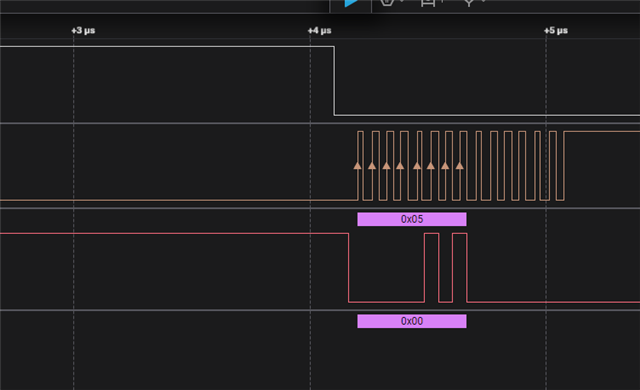
I have followed the QSPI example and the information provided here  Exiting QSPI DPM mode when opening QSPI (memory has been put into DPM previously before QSPI was closed) I can successfully access the QSPI flash, and I can put it in deep power down mode using the code provided, or sending the deep power down command as a QSPI command (CMD_DEEP_PWRDOWN 0xB9).

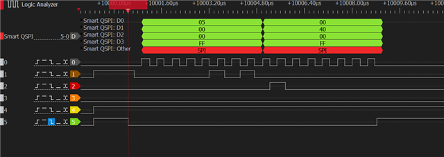
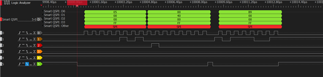
The problem is that this chip, unlike the one in the DK, does not exit deep power down by holding CS high for the proper time, but requires a command (RDP = 0xAB), see 10-4. Release from Deep Power-down (RDP). When I re-initialize the QSPI peripheral with the flash chip in power down, I get a NRF_ERROR_TIMEOUT because the chip doesn't seem to respond to whatever command the QSPI peripheral is using to wake up the device. nrfx_qspi_init fails when executing  NRFX_WAIT_FOR(nrf_qspi_event_check(NRF_QSPI, NRF_QSPI_EVENT_READY), QSPI_DEF_WAIT_ATTEMPTS, QSPI_DEF_WAIT_TIME_US, result);

I'm not sure I understand what nrf_qspi_task_trigger(NRF_QSPI, NRF_QSPI_TASK_ACTIVATE); is doing, but when my flash chip is in deep power down, that never completes and blocks the QSPI peripheral preventing to send any other command

Is there a way to send the 0xAB command to release my flash chip from deep sleep?

Parents
  • Hello,

    I don't have the same flash chip that you are using, but have you tried to use a logic analyzer and capture a logic trace of when the NRF_QSPI_TASKS_ACTIVATE is called? Does it generate any data on the QSPI pins? Have you tried to increase the QSPI_DEF_WAIT_TIME_US from 10 to a higher number? Just for debugging purposes. 

    Also, is it possible to upload the application that you are using to reproduce this issue? 

    Best regards,

    Edvin

  • Thanks for looking into my issue.

    I'm using this code, a small variation of the code linked in the original question

    Fullscreen
    1
    2
    3
    4
    5
    6
    7
    8
    9
    10
    11
    12
    13
    14
    15
    16
    17
    18
    19
    20
    21
    #include <stdio.h>
    #include <string.h>
    #include <stdlib.h>
    #include "nrf_drv_qspi.h"
    #include "nrf_delay.h"
    #include "app_util_platform.h"
    #include "app_error.h"
    #include "boards.h"
    #include "nrf_log.h"
    #include "nrf_log_ctrl.h"
    #include "nrf_log_default_backends.h"
    #include "sdk_config.h"
    #define QSPI_STD_CMD_WRSR 0x01
    #define QSPI_STD_CMD_RSTEN 0x66
    #define QSPI_STD_CMD_RST 0x99
    #define CMD_DEEP_PWRDOWN 0xB9
    #define QSPI_TEST_DATA_SIZE 256
    XXXXXXXXXXXXXXXXXXXXXXXXXXXXXXXXXXXXXXXXXXXXXXXXXX

    This code works for any SPI NOR flash chip that can be released from deep power down using the CS line. For most NOR flash chips, the datasheet says â€śAfter CS# goes high, there is a delay of tRDP before the device transitions from Deep Power-down mode back to Stand-by mode.”

    In the newer 512 Mbit chips (all of them, not just mine), the device doesn't exit deep power down only using the CS line, it explicitly requires a 0xAB instruction to release. Problem is, the QSPI peripheral won't let me send anything, can't even complete the init function.

    I haven't connected a logic analyzer yet, because it would require removing the chip and soldering wires. But from everything I have seen, when initializing the QSPI peripheral, it sends 0x05 to the chip to verify that a chip is connected. In my case, the chip ignores the 0x05 because the only instruction it recognizes is 0xAB. So QSPI times out (I changed QSPI_DEF_WAIT_TIME_US  but it makes no difference, given it's not a real timeout issue)

    I need a way to either change the QSPI peripheral initialization to send 0xAB instead of 0x05, or a way to "trick" the QSPI peripheral to initialize even if the flash chip doesn't reply, so that I can send 0xAB either as a custom instruction or a nrfx_qspi_cinstr_xfer()

    Let me try to convey why this is more than just a minor issue for a specific case: all new 256/512Mbit chips cannot exit deep power down only by using CS, as far as I can tell. They all need the 0xAB instruction (it's done to improve security and avoid exiting low power by  mistake). As such, none of those chips can be properly used by the nRF52840 QSPI when extreme low power is needed.

  • Hello,

    robca said:
    NRF_QSPI->IFCONFIG so I used NRF_QSPI->IFCONFIG1 instead, I'm sure it's just a typo)

    Indeed.

    robca said:
    Is there a way to send 0xAB as a custom QSPI instruction instead of using nrf_drv_qspi_cinstr_xfer()?

    It is not very clear to me. I did see that it is part of the instruction set, but I am not yet sure how this is used.

    Do you have the possiblilty to analyze the QSPI pins using a logic analyzer to see whats actually happens when we try to reinitialize the QSPI and bring the chip back to life?

    I was planning on doing so, but I don't have the QSPI flash chip that you are using. Also, it requires some modifications to the DK (which I can do), but if you have the possibility, it would perhaps give a better picture of what's going on, since it seems to work without issues on my side.

    Or even better, if we can both do it, we can compare the traces to see what it waits for. If not, I need to check if I can get hold of a breakout board with the QSPI chip that you are using. Are you aware of any breakout boards containing the flash chip that you are using?

    Best regards,

    Edvin

  • Once again, I appreciate everything you are doing. And, funny you should ask, but I came to the exact same conclusion: we were flying blind and it was unfair for me to ask you to help without a logic analyzer trace. So I bit the bullet, desoldered the chip and create a horrible rat's nest of bodge wire.

    My logic analyzer channels are: 0 - clock, 1 - DIO0, 2 - DIO1, 3 - DIO2, 4 - DIO3, 5 - CS

    Here's what happens when nrf_drv_qspi_init() runs. The QSPI peripheral actually sends 0x05 (Read Status Register), the EEPROM replies

    Then we have configure_memory. As you can see, every instruction is preceded by sending once more 0x05. It looks as if every instruction starts with 0x05 again, but I'm not sure I understand the 0x06 (Write Enable) before 0x66 (Reset Enable), 0x99 (Reset) and the change to the configuration register 0x01 0x40

    Using your code, the instructions in line 5-12 look like this, i.e. sends yet another 0x05, followed by 0xB9 (deep power down)

    Incidentally, absolutely the same as this code

    Fullscreen
    1
    2
    3
    4
    5
    6
    7
    8
    9
    10
    nrf_qspi_cinstr_conf_t cinstr_cfg = {
    .opcode = CMD_DEEP_PWRDOWN,
    .length = NRF_QSPI_CINSTR_LEN_1B,
    .io2_level = true, // High level during transmission
    .io3_level = true, // High level during transmission
    .wipwait = true,
    .wren = false};
    err_code = nrfx_qspi_cinstr_xfer(&cinstr_cfg, NULL, NULL);
    APP_ERROR_CHECK(err_code);
    XXXXXXXXXXXXXXXXXXXXXXXXXXXXXXXXXXXXXXXXXXXXXXXXXX

    as you can see here

    Good, so now we are in deep sleep.

    Then we get to lines 16-21 in  your code snippet, which is supposed to wake up the EEPROM. As you can see, it simply tries to toggle CS as per the "old" EEPROM convention to exit DPM using only CS  (I needed to use 2 screengrabs due to the different zoom levels, look at the timing on top to make sense of them)

    The device is not out of DPM, though.

    I'm seeing inconsistent results between the device I bodge-wired and another, and I need to do a bit more soldering, but wanted to start capturing some traces and share them.

    Also, if I read the spec sheet correctly, this device should work like mine, and exit DPM only when receiving 0xAB. But I haven't tested it https://www.adafruit.com/product/5634

    To be honest, dead-bug soldering eight 35AWG wires directly the bottom of the WSON-8 version of MX25U51245G is not too bad, so I'm not entirely sure you need a breakout board for the tests

    EDIT: please let me know what traces you need. I'm seeing a slightly different behavior between the board with a dead bug soldered device and the unmodified one. I'm tired now, though, and I'm not sure if I'm doing something else wrong.

    But if there were a way to send 0xAB instead of 0x05 during the qspi init call ,that would solve all problems. Otherwise it looks as if the init returns timeout because there's no reply from the EEPROM

  • wow! This is great! 

    robca said:
    To be honest, dead-bug soldering eight 35AWG wires directly the bottom of the WSON-8 version of MX25U51245G is not too bad,

    I agree that it is doable, but I don't have the chip-only either, so to test properly, I need some HW either way. And the breakout board is easier to re-purpose for different tests that may pop up later. I am sorry, but there is a lot to do, because many of our staff has started their summer holidays. I have modified my DK to be able to analyze the QSPI pins, but I have not yet been able to capture the trace. I will set it up, and see if I get time tonight. 

    I will get back to you with more updates. 

    Best regards,

    Edvin

  • I see the same 0x05 as you see:

    Out of curiousity, does it work if you don't uninit the QSPI? But send the 0xAB like you did with the CMD_DEEP_PWRDOWN packet? I don't know the consequences of this yet, but it is worth a shot just to check that everything else is working as intended.

    edit: Or since we are already at this stage, what happens if you comment out the qspi_ready_wait() in nrfx_qspi_init(), and then send the 0xAB packet?

    Best regards,

    Edvin

  • Problem is: I need to save power, so I need to deinitialize the QSPI peripheral when in low power. Also, it will be disabled anyway when the device goes into sd_power_system_off(), and I need to initialize the QSPI to start sending commands.

    I already tried disabling qspi_ready_wait() in nrfx_qspi_init() (or ignoring the error timeout), but the QSPI peripheral remains in error mode, and doesn't send anything else. Is there a way to clear a pending error?

    The most concerning thing for me now is that I noticed an inconsistency between the board with the dead bug soldering and another board. So I used a PCBite setup on the 4 SPI pins of the QSPI interface, for the non-working board (I only have 4 PCBite probes). Then that board started working, too (DPM and RDP). In the end, I verified that if I have a logic analyzer probe on DIO1, the QSPI peripheral never times out (even when sending 0x05 to a sleeping EEPROM and not receiving 0x40 as a response. Just DIO1, all other pins make no difference.

    I think we used the recommended QSPI pins, minus P0.18 which in the past gave us problems with PINRESET. And those same pins work just fine for everything else, only recover from DPM is a problem.

    #define BSP_QSPI_CSN_PIN P0_16
    #define BSP_QSPI_SCK_PIN P0_19
    #define BSP_QSPI_IO0_PIN P0_21
    #define BSP_QSPI_IO1_PIN P0_22
    #define BSP_QSPI_IO2_PIN P0_23
    #define BSP_QSPI_IO3_PIN P1_00

    My logic analyzer (a DSlogic Plus) has never caused problems before, so I'm a a loss to understand how it could make such a huge difference for QSPI initialization. And I tried with an oscilloscope probe, which also is enough to solve the problem. So there's some hair-trigger logic situation happening (on all boards, also checked)

    Of course if we could clear the QSPI error and send 0xAB after the error, it shouldn't matter

    EDIT:

    And I just found a horrible hack that seems to work. By editing the nrfx_qspi_init() and nrfx_qspi_cinstr_xfer() functions to configure the DIO1 pin as input pulldown (instead of input nopull), the init function returns success, and so does sending 0xAB. Basically, forcing DIO1 low seems to prevent the QSPI peripheral from noticing that the QSPI chip is not responding, until it sends 0xAB and the chip responds again.

    I created a clone of init and xfer, where I define the DIO1 pin as input pulldown on entry and redefine as input no pull on exit. The rest of the library is unchanged. I mean, I guess it could work, but I really don't like this Slight smile. It's "too clever by half" and those things tend to come back and bite.

Reply
  • Problem is: I need to save power, so I need to deinitialize the QSPI peripheral when in low power. Also, it will be disabled anyway when the device goes into sd_power_system_off(), and I need to initialize the QSPI to start sending commands.

    I already tried disabling qspi_ready_wait() in nrfx_qspi_init() (or ignoring the error timeout), but the QSPI peripheral remains in error mode, and doesn't send anything else. Is there a way to clear a pending error?

    The most concerning thing for me now is that I noticed an inconsistency between the board with the dead bug soldering and another board. So I used a PCBite setup on the 4 SPI pins of the QSPI interface, for the non-working board (I only have 4 PCBite probes). Then that board started working, too (DPM and RDP). In the end, I verified that if I have a logic analyzer probe on DIO1, the QSPI peripheral never times out (even when sending 0x05 to a sleeping EEPROM and not receiving 0x40 as a response. Just DIO1, all other pins make no difference.

    I think we used the recommended QSPI pins, minus P0.18 which in the past gave us problems with PINRESET. And those same pins work just fine for everything else, only recover from DPM is a problem.

    #define BSP_QSPI_CSN_PIN P0_16
    #define BSP_QSPI_SCK_PIN P0_19
    #define BSP_QSPI_IO0_PIN P0_21
    #define BSP_QSPI_IO1_PIN P0_22
    #define BSP_QSPI_IO2_PIN P0_23
    #define BSP_QSPI_IO3_PIN P1_00

    My logic analyzer (a DSlogic Plus) has never caused problems before, so I'm a a loss to understand how it could make such a huge difference for QSPI initialization. And I tried with an oscilloscope probe, which also is enough to solve the problem. So there's some hair-trigger logic situation happening (on all boards, also checked)

    Of course if we could clear the QSPI error and send 0xAB after the error, it shouldn't matter

    EDIT:

    And I just found a horrible hack that seems to work. By editing the nrfx_qspi_init() and nrfx_qspi_cinstr_xfer() functions to configure the DIO1 pin as input pulldown (instead of input nopull), the init function returns success, and so does sending 0xAB. Basically, forcing DIO1 low seems to prevent the QSPI peripheral from noticing that the QSPI chip is not responding, until it sends 0xAB and the chip responds again.

    I created a clone of init and xfer, where I define the DIO1 pin as input pulldown on entry and redefine as input no pull on exit. The rest of the library is unchanged. I mean, I guess it could work, but I really don't like this Slight smile. It's "too clever by half" and those things tend to come back and bite.

Children
  • I decided to test with a modified nrfx_qspi.c implementation. I cloned nrfx_qspi_init() into nrfx_qspi_init_rdp() and added the code to configure DIO1 with pulldown, init the QSPI peripheral, then within that same function call nrfx_qspi_cinstr_xfer() with the 0xAB CMD_RELEASE_PWRDOWN command, finally redefining DIO1 as the other QSPI pins. 

    Basically QSPI init for EEPROM devices in Deep Power Down Mode that require 0xAB to exit. I confirmed that when the peripheral sends the first 0x05 with the EEPROM in DPM, the status register reads 0x00 (no data), and as soon as the 0xAB is sent, the EEPROM status reads 0x40. And the QSPI doesn't timeout, even if there's nothing on DIO1. Here's the trace of the nrfx_qspi_init_rdp() call followed by nrfx_qspi_mem_busy_check() (which reads 0x40 as expected)

    I'm posting the modified files for reference. Other people might find this ticket when dealing with modern NOR flash chips. Can't promise it will work in all case, it's not fully tested yet

    nrf_drv_qspi.h

    1
    2
    3
    4
    5
    6
    7
    8
    9
    10
    11
    12
    13
    14
    15
    16
    17
    18
    19
    /**
    * Copyright (c) 2016 - 2021, Nordic Semiconductor ASA
    *
    * All rights reserved.
    *
    * Redistribution and use in source and binary forms, with or without modification,
    * are permitted provided that the following conditions are met:
    *
    * 1. Redistributions of source code must retain the above copyright notice, this
    * list of conditions and the following disclaimer.
    *
    * 2. Redistributions in binary form, except as embedded into a Nordic
    * Semiconductor ASA integrated circuit in a product or a software update for
    * such product, must reproduce the above copyright notice, this list of
    * conditions and the following disclaimer in the documentation and/or other
    * materials provided with the distribution.
    *
    * 3. Neither the name of Nordic Semiconductor ASA nor the names of its
    * contributors may be used to endorse or promote products derived from this
    XXXXXXXXXXXXXXXXXXXXXXXXXXXXXXXXXXXXXXXXXXXXXXXXXX
    nrfx_qspi.h

  • I just realized that this same issue has been found and reported on the Zephyr-based SDK Connect https://github.com/zephyrproject-rtos/zephyr/pull/64782

    Looking at the commit (https://github.com/zephyrproject-rtos/zephyr/commit/1727bbcc7046eb5870df7409310d58e0c9483233), they used a different strategy than mine: instead of defining IO1 as pulldown, the QSPI peripheral is initialized with NRF_QSPI_PIN_NOT_CONNECTED for every pin, the RDP command sent, then QSPI is re-enabled normally

     can you please provide input on the safest way to send an RDP for SDK 17.1.0? Use IO1 pulldown or disconnect the QSPI pins? I do realize that SDK 17.1.0 is in maintenance mode, so I'm not asking for a fix, just an opinion on the best option to work around it.

  • Hello,

    If you are able to make it work while disconnecting the QSPI pins, I would say that this is better. It doesn't require any extra GPIOs, and it doesn't actually output/input a physical signal to a disconnected GPIO.

    It shouldn't really matter, but it sounds "cleaner" in my opinion.

    Best regards,

    Edvin

  • Hey  !

    I just wanted to give a shoutout to your thorough investigation and good find on the zephyr commit! I faced this exact issue with my Seeed XIAO Sense board with the P25Q16H flash on it, but incorporating that trick solved the problem without needing to modify any SDK file. Thx a lot!

    If anyone faces this issue, this is how my fix looks like:

    Fullscreen
    1
    2
    3
    4
    5
    6
    7
    8
    9
    10
    11
    12
    13
    14
    15
    16
    17
    18
    19
    20
    21
    static uint32_t *QSPI_Status_Ptr = (uint32_t*) 0x40029604; // Setup for the SEEED XIAO BLE - nRF52840
    static nrfx_err_t QSPI_IsReady(void) {
    if (((*QSPI_Status_Ptr & 8) == 8) && (*QSPI_Status_Ptr & 0x01000000) == 0) {
    return NRFX_SUCCESS;
    } else {
    return NRFX_ERROR_BUSY;
    }
    }
    static nrfx_err_t QSPI_WaitForReady(void) {
    while (QSPI_IsReady() == NRFX_ERROR_BUSY) {
    // TODO timeout
    }
    return NRFX_SUCCESS;
    }
    static nrfx_err_t QSPI_RDPWorkaroundInit(void) {
    nrfx_err_t err_code;
    nrf_qspi_pins_t pins;
    nrf_qspi_pins_get(NRF_QSPI, &pins);
    XXXXXXXXXXXXXXXXXXXXXXXXXXXXXXXXXXXXXXXXXXXXXXXXXX