Hello,
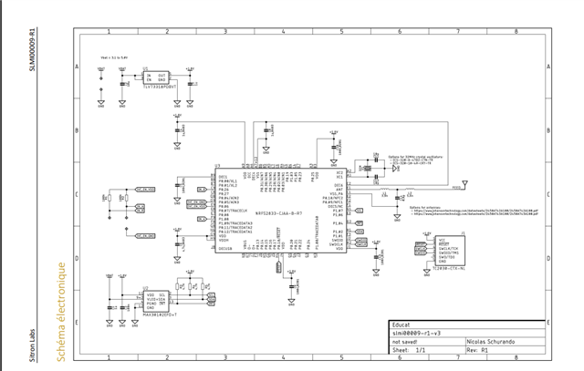
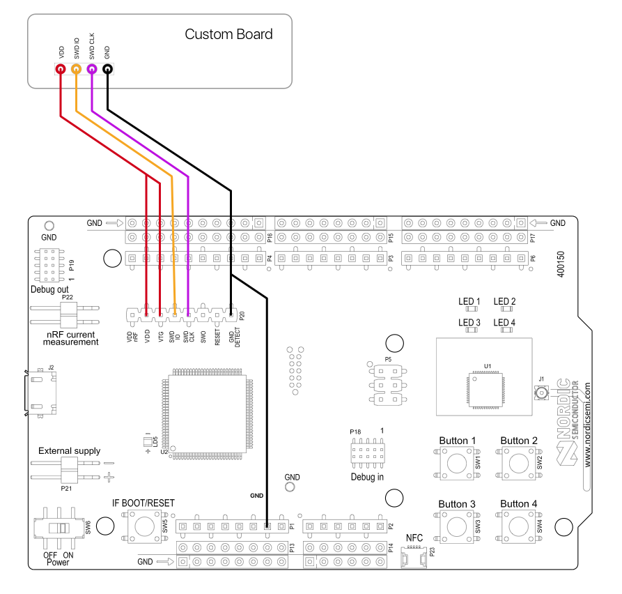
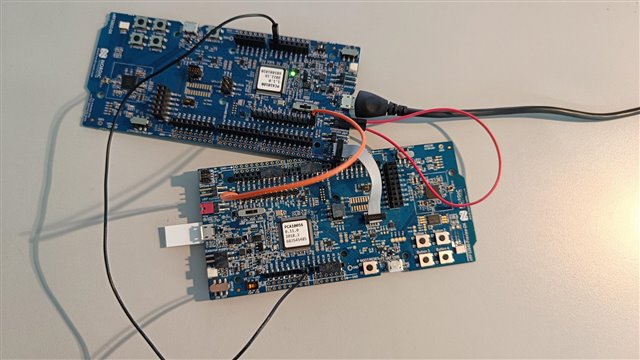
When we flash the BLE Zephyr project to the external chip (nRF52833), do we need to add the SoftDevice controller .hex file as well, or does the merged .hex file include everything necessary?
Thank you.
Hello,
When we flash the BLE Zephyr project to the external chip (nRF52833), do we need to add the SoftDevice controller .hex file as well, or does the merged .hex file include everything necessary?
Thank you.